Installation 5
0020261188_00 ecoTEC plus Installation and maintenance instructions 11
Reference
number for
the basic
diagram
Control
system
Number
of cir-
cuits
Carrying out the
wiring
0020253233 Basic control 1 See appendix.
0020253235 VRC 700
system
control
1 Observe the instruc-
tions for the system
control.
0020253236 eRELAX
connected
control
1 Observe the instruc-
tions for the system
control.
Note
The example of a basic installation diagram that
is shown in the appendix does not replace any
correct and expert system planning. (→ Page 49)
The settings for the internal pump are made at the factory.
▶ Ensure that there is sufficient dimensioning for the
connections and the domestic hot water cylinder.
(→ Page 13)
▶ Connect the external prioritising diverter valve to the plug
X13 on the main PCB.
▶ In order to control the cylinder's post-heating, connect
a VR 10 temperature sensor or a thermostat to the plug
that is connected to the main PCB.
Wiring diagram (→ Page 47)
To start up the prioritising diverter valve, it is not necessary
to set a diagnostics code. It is directly actuated by the pro-
duct's main PCB.
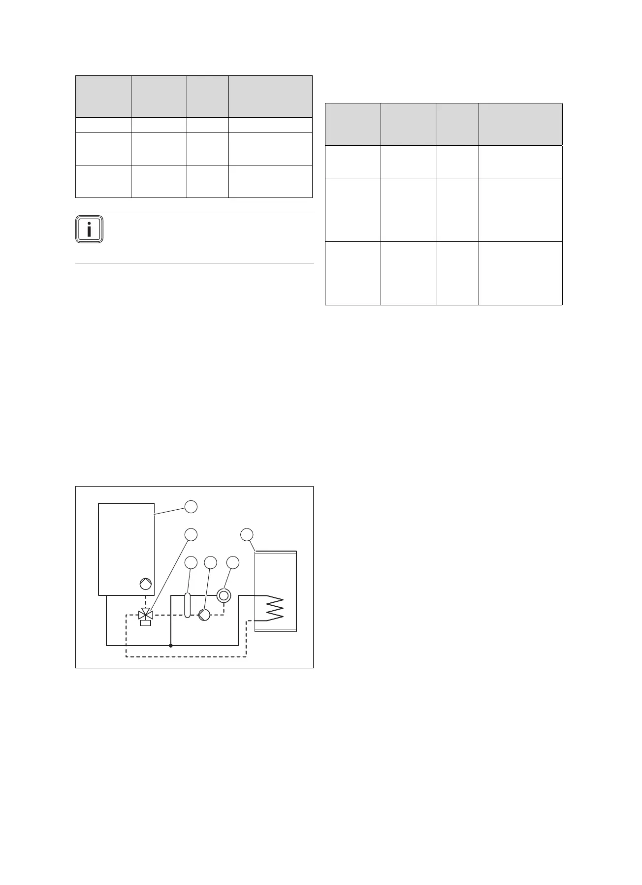
5.1.2 Basic system diagram type 2: Decoupled
heating circuit plus one directly connected
domestic hot water cylinder
1 Wall-hung boiler with
internal pump
2 Prioritising diverter
valve
3 Low loss header or
plate heat exchanger
4 External pump for the
decoupled heating
circuit
5 Heating circuit
6 Domestic hot water
cylinder
▶ In order to use this basic diagram type, ensure that the
minimum flow volumes are guaranteed for the operation.
(→ Page 53)
The product can control a decoupled heating circuit and a
directly connected domestic hot water cylinder.
Reference
number for
the basic
diagram
Control
system
Number
of cir-
cuits
Carrying out the
wiring
0020253238 VRC 700
system
control
1 Observe the instruc-
tions for the system
control.
0020253239 VRC 700
system
control
VR 70 multi-
functional
module
2 Observe the instruc-
tions for the system
control.
0020259027 VRC 700
system
control
VR 71 multi-
functional
module
>3 Observe the instruc-
tions for the system
control.
The settings for the internal pump are made at the factory.
▶ Ensure that there is sufficient dimensioning for the
connections and the domestic hot water cylinder.
(→ Page 13)
▶ Downstream of the low loss header, select a heating
pump that is appropriate for the installation.
▶ Connect the external pump for the decoupled heating
circuit to the plug X16 for the main PCB.
▶ Connect the external prioritising diverter valve to the plug
X13 on the main PCB.
▶ Connect the temperature sensor for the low loss header
to plug X41 on the main PCB. Observe the instructions
for the low loss header.
▶ In order to control the cylinder's post-heating, connect
a VR 10 temperature sensor or a thermostat to the plug
that is connected to the main PCB.
Wiring diagram (→ Page 47)
▶ Set diagnostics code D.026 to 2.
Overview of diagnostics codes (→ Page 39)

 Loading...