4 Set-up
8 Installation and maintenance instructions ecoTEC plus 0020261188_00
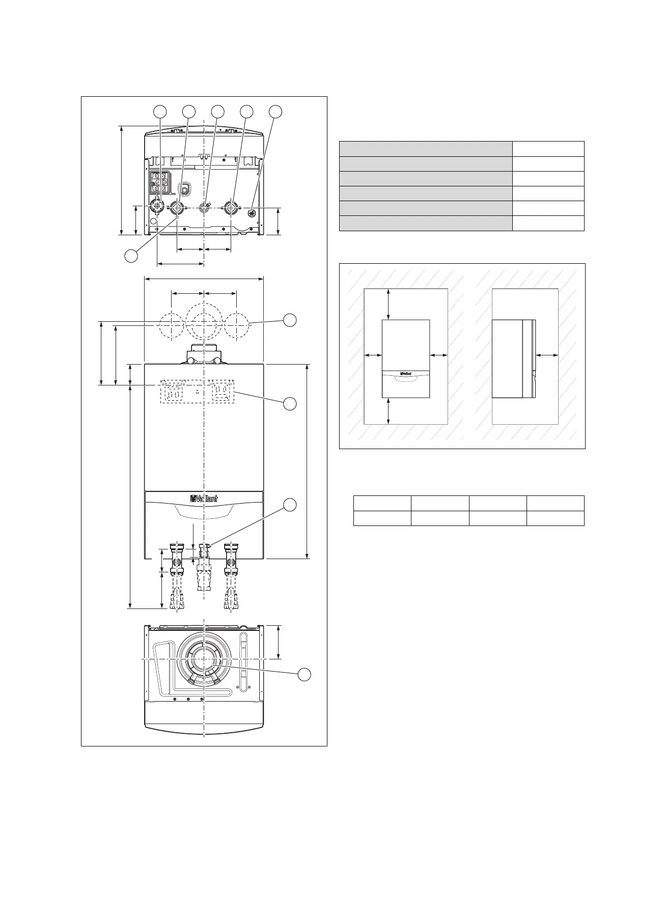
4.3 Dimensions
108
100
A
100 100
173
440
125
78
720
220
235
120120
85,5133,8
29,5
825
6
1
2 3
9
10
4 5
7
8
1 Condensate siphon
2 Heating flow connection
3 Gas connection
4 Heating return connec-
tion
5 Drain for the rainwater
collecting device
6 Position of the holes for
the flue system
7 Retainer for securing
the product
8 Gas pressure connec-
tion
9 Connection for the
air/flue pipe
10 Drain for the dynamic
air separation system
Dimension A
VC 406/5-5 (E-DE)
405 mm
VC 406/5-5 (LL-DE)
405 mm
VC 476/5-5 (E-DE)
405 mm
VC 476/5-5 (LL-DE)
405 mm
VC 636/5-5 (E-DE)
473 mm
VC 636/5-5 (LL-DE)
473 mm
4.4 Minimum clearances
▶ When using the accessories, observe the minimum clear-
ances/installation clearances.
Minimum clearances
A B C D
≥ 275 mm ≥ 180 mm ≥ 5 mm ≥ 500 mm
– Optimum dimension (B): ≈ 250 mm
– Optimum dimension (C): ≈ 50 mm
– Dimension (D): The clearance in front of the product
to facilitate easy access for maintenance work can
be reduced to 5 mm if there is a door in front of the
product
4.5 Clearance from combustible components
It is not necessary to maintain a clearance between the
product and components made of combustible materials that
go beyond the minimum clearances.
4.6 Using the mounting template
▶ Use the mounting template to ascertain the locations at
which you need to drill holes and make breakthroughs.

 Loading...