Installation 5
0020261188_00 ecoTEC plus Installation and maintenance instructions 13
▶ In order to control the cylinder's post-heating, connect
a VR 10 temperature sensor or a thermostat to the plug
that is connected to the main PCB.
Wiring diagram (→ Page 47)
▶ Set diagnostics code D.026 to 1.
Overview of diagnostics codes (→ Page 39)
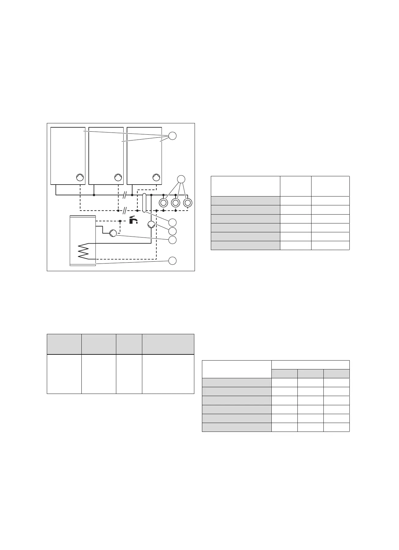
5.1.5 Basic system diagram type 5: Cascade with
two to seven boilers + a cylinder that is
connected to the heating circuit
1 Wall-hung boiler with
internal pump
2 Heating circuits
3 Low loss header or
plate heat exchanger
4 External pump for the
decoupled domestic hot
water circuit
5 External domestic hot
water circulation pump
6 Domestic hot water
cylinder
The product can control a cascade system.
Number for
the basic
diagram
Control
system
Number
of cir-
cuits
Wiring
0020259033 VRC 700
system
control
VR 71 multi-
functional
module
>3 See the instructions
for the system con-
trol.
The settings for the internal pump are made at the factory.
▶ Ensure that there is sufficient dimensioning for the
connections and the domestic hot water cylinder.
(→ Page 13)
▶ Downstream of the low loss header, select a domestic
hot water pump that is suitable for the domestic hot water
cylinder.
▶ Connect the pump for the decoupled domestic hot water
circuit to the plug X13 for the main PCB.
▶ Connect the temperature sensor for the low loss header
to plug X41 on the main PCB. Observe the instructions
for the low loss header.
▶ In order to control the cylinder's post-heating, connect
a VR 10 temperature sensor or a thermostat to the plug
that is connected to the main PCB.
Wiring diagram (→ Page 47)
▶ Set diagnostics code D.026 to 1.
Overview of diagnostics codes (→ Page 39)
5.2 Selecting the domestic hot water cylinder
The product can control an optional domestic hot water cylin-
der (recommended option for products with an output below
50 kW).
▶ Use a low loss header for products that are connected to
a domestic hot water cylinder and have a domestic hot
water output requirement of over 50 kW, . (→ Page 13)
▶ Use the following components to connect the domestic
hot water cylinder:
Domestic hot water cylinder
Cylinder Internal dia-
meter of the
connection
VC 406/5-5 (E-DE)
VIH R 300 20 mm
VC 406/5-5 (LL-DE)
VIH R 300 20 mm
VC 476/5-5 (E-DE)
VIH R 300 20 mm
VC 476/5-5 (LL-DE)
VIH R 300 20 mm
VC 636/5-5 (E-DE)
VIH R 500 25 mm
VC 636/5-5 (LL-DE)
VIH R 500 25 mm
5.3 Selecting a low loss header
The low loss header disconnects the heat generator hydraul-
ically from the heating system. This prevents feed head in-
teractions between the individual circulation pumps. Further-
more, the low loss header ensures that a sufficient minimum
volume of water continuously circulates through the heat
generator.
▶ Observe the information on treating heating water.
(→ Page 19)
▽ If you cannot guarantee the conditions for treating
the heating water, install an external plate heat ex-
changer to protect the product.
Low loss header
Heating system spread
10 K 15 K 20 K
VC 406/5-5 (E-DE)
WH 95 WH 40-2 WH 40-2
VC 406/5-5 (LL-DE)
WH 95 WH 40-2 WH 40-2
VC 476/5-5 (E-DE)
WH 95 WH 40-2 WH 40-2
VC 476/5-5 (LL-DE)
WH 95 WH 40-2 WH 40-2
VC 636/5-5 (E-DE)
WH 160 WH 95 WH 40-2
VC 636/5-5 (LL-DE)
WH 160 WH 95 WH 40-2
▶ Observe the instructions for the low loss header.
You do not require any electronic accessories when using
a low loss header. You can connect simple installations dir-
ectly inside the electronics box.
▶ Observe the wiring diagram.

 Loading...