Notes on the documentation 1
0020266269_01 Operating and installation instructions 13
Operating and installation
instructions
1 Notes on the documentation
1.1 Observing other applicable documents
▶ Always observe all the operating and installation instruc-
tions included with the system components.
1.2 Validity of the instructions
These instructions apply only to:
Product article number
VR 920
0020252922, 0020252923,
0020252924, 0020252926
VR 921
0020260962, 0020260963,
0020260964, 0020260965,
0020282696
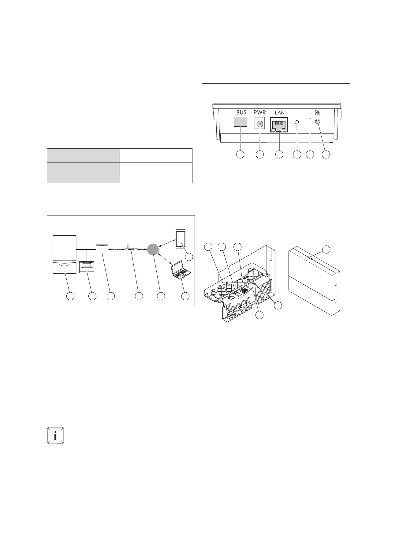
2 System overview
1 Heat generator (eBUS-
compatible)
2 System control
3 VR920 or VR921 com-
munication unit
4 Internet router
5 Vaillant Group server
6 multiMATIC app or
sensoAPP
7 profiDIALOG remote
service and diagnosis
platform
The communication unit is the central Vaillant gateway to the
Internet and enables Connectivity Services.
The multiMATIC app is only compatible with the
multiMATIC VRC700 system control and supports Apple
iOS and Android smartphones.
The sensoAPP app is compatible with the sensoCOMFORT
VRC720 and sensoHOME VRT380 controls and supports
Apple iOS and Android smartphones.
Note
Using the communication unit produces data
traffic. We recommend using an Internet flat rate
tariff.
3 Product description
3.1 Product design
3.1.1 VR 920
1 BUS (eBUS connection
to the heat generator)
2 Power supply unit con-
nection
3 Network cable connec-
tion
4 Status LED
5 Reset knob
6 Radio link start-up
button
3.1.2 VR 921
1 BUS (eBUS connection
to the heat generator)
2 Power supply unit con-
nection
3 Network cable connec-
tion
4 Status LED
5 Radio link start-up
button
6 Reset knob
3.2 Product functions
The communication unit can be connected to the Internet
via WLAN or LAN. The communication unit has a wireless
interface for using the ambiSENSE single-room temperature
control.
If you want to use the WLAN and ambiSENSE wireless in-
terfaces, you must remove the communication unit from the
boiler and position it on the boiler (applies only for the VR
920 built-in version).
If you want to use the LAN interface only, the communication
unit can remain in the boiler (applies only for the VR 920
built-in version).