________________________________________________________________________________
VAISALA________________________________________________________________________ 7
List of Figures
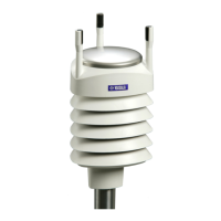
Figure 1 Vaisala Weather Transmitter WXT520. . . . . . . . . . . . . . . . . . . 17
Figure 2 Main Components of Weather Transmitter WXT520 . . . . . . . . 19
Figure 3 Cut Away View . . . . . . . . . . . . . . . . . . . . . . . . . . . . . . . . . . . . . 20
Figure 4 Bottom of Transmitter. . . . . . . . . . . . . . . . . . . . . . . . . . . . . . . . 21
Figure 5 Mounting Kit (Optional) . . . . . . . . . . . . . . . . . . . . . . . . . . . . . .22
Figure 6 USB Cables (optional). . . . . . . . . . . . . . . . . . . . . . . . . . . . . . .22
Figure 7 Bird Spike Kit (optional) . . . . . . . . . . . . . . . . . . . . . . . . . . . . . . 23
Figure 8 Surge Protector (optional) . . . . . . . . . . . . . . . . . . . . . . . . . . . . 24
Figure 9 Heating Control . . . . . . . . . . . . . . . . . . . . . . . . . . . . . . . . . . . . 30
Figure 10 Recommended Mast Location in an Open Area . . . . . . . . . . . 32
Figure 11 Recommended Mast Length on Top of a Building . . . . . . . . . .33
Figure 12 Location of Fixing Screw . . . . . . . . . . . . . . . . . . . . . . . . . . . . . 35
Figure 13 Mounting WXT520 to Pole Mast Using Optional Mounting
Kit. . . . . . . . . . . . . . . . . . . . . . . . . . . . . . . . . . . . . . . . . . . . . . .36
Figure 14 Mounting WXT520 to Cross Arm (L-Profile). . . . . . . . . . . . . . . 37
Figure 15 Mounting Bolt Location in Cross Arm. . . . . . . . . . . . . . . . . . . . 38
Figure 16 Grounding Using the Bushing and Grounding Kit . . . . . . . . . . 39
Figure 17 Grounding Jumper Location. . . . . . . . . . . . . . . . . . . . . . . . . . . 40
Figure 18 Sketch of Magnetic Declination . . . . . . . . . . . . . . . . . . . . . . . .41
Figure 19 Wind Direction Offset . . . . . . . . . . . . . . . . . . . . . . . . . . . . . . . . 42
Figure 20 Average Operational Current Consumption (with 4Hz
Wind Sensor Sampling) . . . . . . . . . . . . . . . . . . . . . . . . . . . . . . 44
Figure 21 Heating Current and Power vs Vh . . . . . . . . . . . . . . . . . . . . . . 45
Figure 22 Pins of 8-pin M12 Connector . . . . . . . . . . . . . . . . . . . . . . . . . . 46
Figure 23 Internal Wiring . . . . . . . . . . . . . . . . . . . . . . . . . . . . . . . . . . . . .47
Figure 24 Screw Terminal Block . . . . . . . . . . . . . . . . . . . . . . . . . . . . . . .48
Figure 25 Data Communication Interfaces. . . . . . . . . . . . . . . . . . . . . . . . 50
Figure 26 Replacing the PTU Module . . . . . . . . . . . . . . . . . . . . . . . . . .130
Figure 27 Accuracy Over Temperature Range . . . . . . . . . . . . . . . . . . . 140
Figure 28 WXT520 Dimensions, Side View . . . . . . . . . . . . . . . . . . . . . . 146
Figure 29 WXT520 Dimensions, Top and Bottom View . . . . . . . . . . . . .147
Figure 30 Mounting Kit Dimensions . . . . . . . . . . . . . . . . . . . . . . . . . . . . 148
Figure 31 Timing Diagram . . . . . . . . . . . . . . . . . . . . . . . . . . . . . . . . . . .159
Figure 32 Wind Measurement Averaging Method . . . . . . . . . . . . . . . . . 164