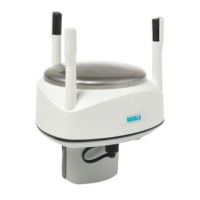
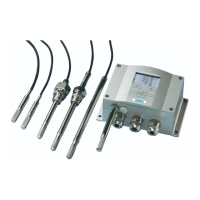
Do you have a question about the Vaisala WXT536 and is the answer not in the manual?
Highlights important safety considerations throughout the manual.
Details electrostatic discharge prevention to protect electronic circuits.
Provides information on standard warranty terms and conditions.
Explains Vaisala WINDCAP sensor technology for wind speed and direction measurement.
Details the RAINCAP Sensor 2-technology for precipitation measurement.
Describes the sensors for pressure, temperature, and humidity measurement.
Explains how heating elements keep sensors clean from snow and ice.
Guides on selecting a representative site for ambient measurements following WMO guidelines.
Provides instructions for mounting, grounding, and connecting the transmitter.
Explains the ease of mounting the transmitter on a vertical pole mast or horizontal cross arm.
Explains typical grounding methods for the transmitter.
Details current consumption and power supply requirements for the transmitter.
Explains external wiring using the 8-pin M12 connector.
Provides instructions for wiring using the internal screw terminals.
Illustrates the data communication interfaces available for the transmitter.
Offers hints for economic power management based on operating mode.
Lists available communication protocols for each serial interface.
Explains how to connect and use the USB service cable.
Details connecting through the M12 connector or screw terminal for settings.
Explains commands to check and change communication settings.
Describes general commands, including the reset command (aXZ).
Covers checking and changing wind sensor settings.
Details checking and changing PTU sensor settings.
Explains checking and changing precipitation sensor settings.
Covers checking and changing supervisor settings.
Lists common communication problems and their solutions.
| Measurement Parameters | Wind speed, Wind direction, Temperature, Humidity, Pressure, Precipitation |
|---|---|
| Humidity Range | 0 to 100 %RH |
| IP rating | IP66 |
| Accuracy - Wind direction | ±3 ° |
| Wind Speed Range | 0 to 60 m/s |
| Wind Direction Range | 0 to 360 ° |
| Pressure Range | 600 to 1100 hPa |
| Rainfall Intensity Range | 0 ... 200 mm/h |
| Communication Interface | RS-232, RS-485 |
| Accuracy - Wind speed | ±0.3 m/s |
| Accuracy - Temperature | ±0.3 °C |
| Accuracy - Pressure | ±0.5 hPa |
| Accuracy - Rainfall | ± 5 % |
| Temperature Range | -52 to +60°C |
| Operating Temperature | -52 to +60°C |
| Accuracy - Humidity | ±3 %RH (0 ... 90 %RH) ±5 %RH (90 ... 100 %RH) |


