Chapter 8 ____________________________________________ Sensor and Data Message Settings
VAISALA______________________________________________________________________ 149
Analog Input
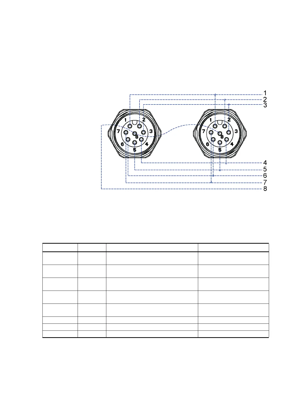
The pins of the analog input connectors are shown below.
1510-006
Figure 37 Analog Input Connector Pins
The following table describes analog input signal names and
descriptions.
Table 21 Analog Input Signals
Signal name M12 Pin Description Use example
PTI+ 1 PT1000 measuring current PT1000 temperature sensor
Current feed
PT+ 2 PT1000 input+ PT1000 temperature sensor.
Sense+
PT- 3 PT1000 input- PT1000 temperature sensor
Sense-
AGND 4 Analog ground Common ground for level,
tipping bucket, and PT1000
TIP IN 5 Pulse counting input (pulled up with
resistor)
Tipping bucket type rain
sensor
SR+ 6 Differential 0 ... 25 mV input, + Pyranometer
SR- 7 Differential 0 ... 25 mV input, - Pyranometer
WS IN 8 0 ... 2.5/0 ... 5/0 ... 10 V input Water/snow level sensor