Do you have a question about the Vaisala HUMICAP HMT330 SERIES and is the answer not in the manual?
| Humidity Measurement Range | 0 ... 100 %RH |
|---|---|
| Protection Class | IP65 |
| Measurement Parameters | Relative Humidity, Temperature |
| Temperature Measurement Range | -40 to +60 °C |
| Humidity Accuracy | ±1 %RH (0 ... 90 %RH) ±1.7 %RH (90 ... 100 %RH) |
| Temperature Accuracy | ±0.2 °C |
| Humidity Sensor | HUMICAP® |
| Output Signals | Analog |
| Power Supply | 10...35 VDC |
| Operating Temperature Range | -40 to +60 °C |
Provides information for installing, operating, and maintaining the Vaisala HMT330.
Details manual code, description, and previous versions of the documentation.
Explains how warnings, cautions, and notes are highlighted within the manual.
Covers general safety precautions for the HMT330 transmitter.
Describes precautions to prevent Electrostatic Discharge damage to electronic circuits.
Provides instructions on recycling materials and proper disposal of batteries and units.
Lists EU directives and standards the HMT330 transmitter conforms to.
Details the DNV type approval for the HMT330 series, including application and location classes.
FCC compliance statements for transmitters equipped with LAN or WLAN interfaces.
Lists patents protecting the HMT330 Series and registered trademarks.
Outlines software usage rights and provides information on standard warranty terms.
Introduces the HMT330 transmitter's measurement capabilities and options.
Lists key features, application benefits, and optional modules for the HMT330.
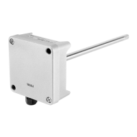
Details the physical components and labeling of the transmitter body.
Describes the different probe types available for the HMT331 transmitter.
Explains the function and application of the HMT337 warmed probe.
Covers methods for mounting the transmitter housing without a mounting plate.
Details how to mount the transmitter housing directly to a wall using screws.
Explains how to mount the transmitter using a wall mounting kit.
Details DIN rail and pole/pipeline installation methods.
Explains mounting the rain shield and using a panel mounting frame.
Covers cable installation, bushings, and grounding for optimal performance.
Covers wiring connections for power supply and signal terminals on the motherboard.
Explains connecting the transmitter to a 24 VAC power supply, including considerations.
Emphasizes matching probe and environment temperatures for accurate humidity measurements.
Provides guidance on horizontally mounting probes with cables to prevent water ingress.
Details installation for HMT333, HMT334, HMT335, HMT337, and HMT338 probes.
Provides step-by-step instructions for tightening the probe clasp nut correctly.
Details the installation process for various optional modules.
Step-by-step guide for installing the power supply module into the transmitter housing.
Lists safety warnings related to power supply module installation.
Explains the optional output isolation module to prevent grounding loops.
Provides instructions for installing and wiring the analog output module.
Details relay module installation and selecting the activation state.
Describes the RS-422/485 interface installation and wiring.
Details the optional LAN interface for Ethernet connectivity and its network settings.
Describes the optional WLAN interface for wireless connectivity and security.
Instructions for attaching the WLAN antenna to the transmitter cover.
Explains the data logger module for extending data storage and its specifications.
Provides the pinout definition for the optional 8-pin connector.
Guides initial power-up, language selection, and basic transmitter operation.
Describes the graphical display for viewing data trends or min/max values over time.
Covers changing language, rounding, and backlight settings via display/keypad.
Instructions for adjusting display contrast and locking the keypad.
Describes activating a PIN lock to prevent unauthorized access to device settings.
Guides on restoring factory defaults and configuring display alarms.
Provides instructions for setting up and configuring display alarms for the transmitter.
Explains using the MI70 Link program for monitoring and transferring transmitter data.
Describes connecting via User Port or Service Port for serial line communication.
Explains User Port operating modes and default communication settings.
Covers connecting to the Service Port and installing USB drivers.
Explains enabling LAN communication and configuring IP settings.
Guides on configuring IP settings using the transmitter's display and keypad.
Explains how to configure network settings for LAN/WLAN using serial line commands.
Details wireless LAN settings, including SSID and security types.
Guides on configuring wireless LAN settings using the display/keypad.
Explains configuring wireless network settings using serial line commands.
Describes setting communication protocols and modes for LAN/WLAN interfaces.
Explains accessing and using the web interface for configuring LAN and WLAN settings.
Provides instructions for connecting to the HMT330 using a terminal program.
Details the steps for establishing a serial or USB connection using PuTTY.
Guides on establishing a Telnet session for LAN/WLAN connections using PuTTY.
Lists and describes serial commands for measurement, communication, and formatting.
Explains how to retrieve measurement data from the transmitter via a serial line.
Covers formatting serial line messages using FTIME, FDATE, and FST commands.
Guides on changing display quantities, units, and general settings.
Explains the importance of process pressure and how to set it for humidity calculations.
Details how to set the date and time using the display/keypad or serial commands.
Explains the averaging data filter and its three available levels.
Explains how to display device information using the keypad or serial line.
Explains the '?' command for configuration and LIGHT command for backlight.
Lists commands for help, error messages, version info, and device reset.
Explains how to lock keypad/menu access using LOCK command, with optional PIN.
Covers changing serial output settings via display/keypad or serial line.
Explains how to set the user port start-up operating mode (STOP, RUN, etc.).
Describes how to set the transmitter's device address for POLL and MODBUS modes.
Describes data recording and how collected data can be accessed.
Explains viewing and managing recorded data files, including deletion.
Covers changing analog output settings, including mode and range.
Guides on changing and scaling analog output quantities via display/keypad.
Explains how to select and scale analog output quantities using AMODE and ASEL.
Describes testing analog output operation by forcing values and measuring them.
Explains setting the analog output fault indication value.
Details relay operation modes, setpoints, hysteresis, and enabling/disabling.
Describes how relays can indicate the transmitter's operational status (FAULT/ONLINE).
Introduces MODBUS protocol support, including variants and connections.
Outlines the configuration steps required to use the MODBUS protocol.
Details software settings for enabling MODBUS over RS-232 or RS-485.
Details software settings for enabling MODBUS TCP (Ethernet).
Explains how to use diagnostic counters to identify MODBUS communication problems.
Instructions on how to disable the MODBUS protocol and switch to another mode.
Covers routine maintenance including cleaning and filter replacement.
Explains how and when to change the humidity sensor, and post-replacement calibration.
Describes how the transmitter indicates and displays error states.
Provides contact information for technical support and product return procedures.
Steps to open and close the transmitter's adjustment mode using motherboard buttons.
Guides on performing RH calibration using push buttons, keypad, or serial line.
Details the FCRH command for RH adjustment after sensor replacement.
Explains temperature calibration using display/keypad or serial line commands.
Details calibrating analog outputs by forcing values and measuring with a multimeter.
Explains how to enter calibration information (date, text) into the transmitter's memory.
Lists performance data including relative humidity range, accuracy, and response times.
Provides temperature operating ranges and pressure limits for various probes.
Lists specifications for the optional temperature probe.
Lists typical measurement ranges for calculated variables like dewpoint and mixing ratio.
Details accuracies for calculated variables based on sensor calibration.
Lists operating and storage temperature ranges, and humidity limits.
Details electrical inputs, outputs, and communication protocols.
Provides mechanical specifications including cable bushings, connectors, and probe dimensions.
Lists transmitter weight based on probe type and cable length.
Lists technical specifications for Power Supply, Analog Output, Relay, RS-485, LAN, WLAN, and Data Logger modules.
Lists available optional modules and accessories with their order codes.
Provides detailed physical dimensions of the transmitter body and probes.
Describes duct installation kits for HMT333, HMT337, and HMT335 probes.
Details the duct installation kit for the temperature probe (T-probe) on HMT337.
Explains Swagelok installation kits for RH and Temperature probes.
Illustrates vapor-tight installations for RH probes using a cable gland.
Provides examples of T-probe installations, including vapor tight and wall mounting.
Shows an example of installing the transmitter in a climate chamber.
Illustrates an example of installing the transmitter through a roof.
Details the ball valve installation kit for connecting the HMT338 probe to pressurized systems.
Describes the meteorological installation kit for outdoor HMT337 installations.
Presents the formula used to calculate dewpoint temperature from measured values.
Presents the formula used to calculate mixing ratio from measured values.
Presents the formula used to calculate absolute humidity from measured values.
Presents the formula used to calculate enthalpy from measured values.
Lists supported MODBUS function codes and their corresponding notes and classes.
Describes the MODBUS register map, grouping data into contiguous blocks.
Explains numeric data formats (IEEE float, signed integer) used in MODBUS.
Explains the 16-bit integer format, scaling, negative values, and wrapping.
Lists MODBUS registers for measurement data, including float and integer formats.
Lists MODBUS registers for transmitter status information like fault and online status.
Lists MODBUS registers used for configuring measurement parameters.
Explains exception status outputs and their relation to transmitter status.
Describes MODBUS diagnostic functions accessed via function code 08.
Lists MODBUS device identification objects conforming to standard specifications.
Describes MODBUS exception responses according to the protocol specification.