Do you have a question about the Vaisala HUMICAP HMW90 SERIES and is the answer not in the manual?
| Brand | Vaisala |
|---|---|
| Model | HUMICAP HMW90 SERIES |
| Category | Transmitter |
| Language | English |
Provides an overview of the manual's scope and content for HMW90 series transmitters.
Lists the chapters and appendices covered in the manual.
Details manual revisions and associated dates and changes.
Lists other relevant Vaisala documentation for HMW90 series.
Explains how warnings, cautions, and notes are used in the manual.
Outlines critical safety instructions for handling and operating the transmitter.
Guidelines for preventing electrostatic discharge damage to electronic components.
Information on proper disposal and recycling of the unit.
Lists standards and directives the HMW90 series complies with.
Information on patents protecting the HMW90 series.
Lists registered trademarks used in the manual.
Terms governing the use of software included with the product.
Details on product warranty terms and conditions.
Overview of the HMW90 series transmitters and their common features.
Lists and describes different models within the HMW90 series.
Explains the various parameters the HMW90 series can measure and output.
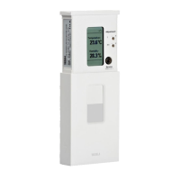
Identifies and describes the external components of the transmitter.
Guidance on changing transmitter settings prior to installation.
Describes methods for configuring analog output models.
Details the function of DIP switches for analog output configuration.
Explains how to configure the relay using DIP switches and rotary switch.
Outlines configuration interfaces for digital output models.
Explains DIP switch settings for digital output models, including protocol and address.
Information on setting the MAC address for BACnet MS/TP.
Information on setting the MAC address for Modbus slaves.
Recommendations for optimal placement of the transmitter for accurate measurements.
Wiring instructions specific to the HMW92 model.
Wiring instructions specific to the HMW93 model.
Wiring instructions specific to the TMW92 model.
Wiring instructions specific to the TMW93 model.
Guidance on connecting multiple transmitters to a common AC power supply.
Wiring instructions specific to the HMW95 model.
Instructions for wiring several HMW95 transmitters on the same RS-485 line.
Covers startup screens, measurement display, and on-screen indicators.
Instructions for connecting via MI70 indicator or PC, including driver and terminal settings.
Guide to using serial commands for transmitter operation and configuration.
Setting environmental parameters and selecting measurement units.
Setting analog output modes, scaling, clipping, and error limits.
Selecting which parameters are shown on the transmitter's display.
Commands to start/stop measurements, output readings, set intervals, and define output formats.
Configuring remote echo and serial line response time.
Setting relay modes, parameters, and limits in custom mode.
Procedures for adjusting humidity and temperature measurements.
Commands for testing analog outputs and relay operations.
Routine tasks for maintaining the transmitter's condition.
How to clean the transmitter body.
Overview of calibration and adjustment options for the transmitter.
How to perform adjustments using the transmitter's display and trimmers.
Steps for calibrating and adjusting the transmitter with an HM70 meter.
Procedures for calibrating and adjusting the transmitter via a PC.
Procedures for repairing the transmitter.
Instructions for replacing the humidity and temperature measurement module.
Lists common issues and their possible causes and solutions.
Explains error messages that appear on the transmitter's display.
Explains error messages communicated via the serial line.
Command to view active errors on the serial line.
Command to view a table of possible transmitter errors.
How analog outputs behave when critical or error level errors are active.
Steps to reset the transmitter to factory default configuration using DIP switches.
Steps to reset the transmitter to factory default configuration via the service port.
Contact information and required details for technical support.
Information on returning the product for service or repair.
Details on measurement ranges, accuracy, and stability of the transmitter.
Lists available spare parts and accessories with their order codes.
Provides physical dimensions of the transmitter and mounting base.
Conformance statement for BACnet standard compliance.
Describes the properties of the BACnet device object.
Details the BACnet object identifier for the device.
Specifies the BACnet object name for the device.
Indicates the operational status of the BACnet device.
Lists supported BACnet protocol services.
Properties of the BACnet Relative Humidity object.
Properties of the BACnet Temperature object.
Properties of the BACnet Operation Pressure object.
Properties of the BACnet Operation Altitude object.
Lists supported BACnet Interoperability Building Blocks (BIBBs).
Lists supported BACnet standard application services.
Lists the Modbus function codes supported by the HMW90 series.
Describes the contiguous blocks of registers for Modbus data.
Explains the formats for numeric values (floating point, integer).
Details the representation of 32-bit IEEE floating point values.
Details the representation of 16-bit signed integer values.
Modbus registers for reading measurement data.
Modbus registers for reading transmitter status.
Modbus registers used for configuring the measurement.
Modbus objects for device identification information.
Explains Modbus exception codes and their meanings.