Chapter 3 ________________________________________________________________ Installation
VAISALA ________________________________________________________________________ 33
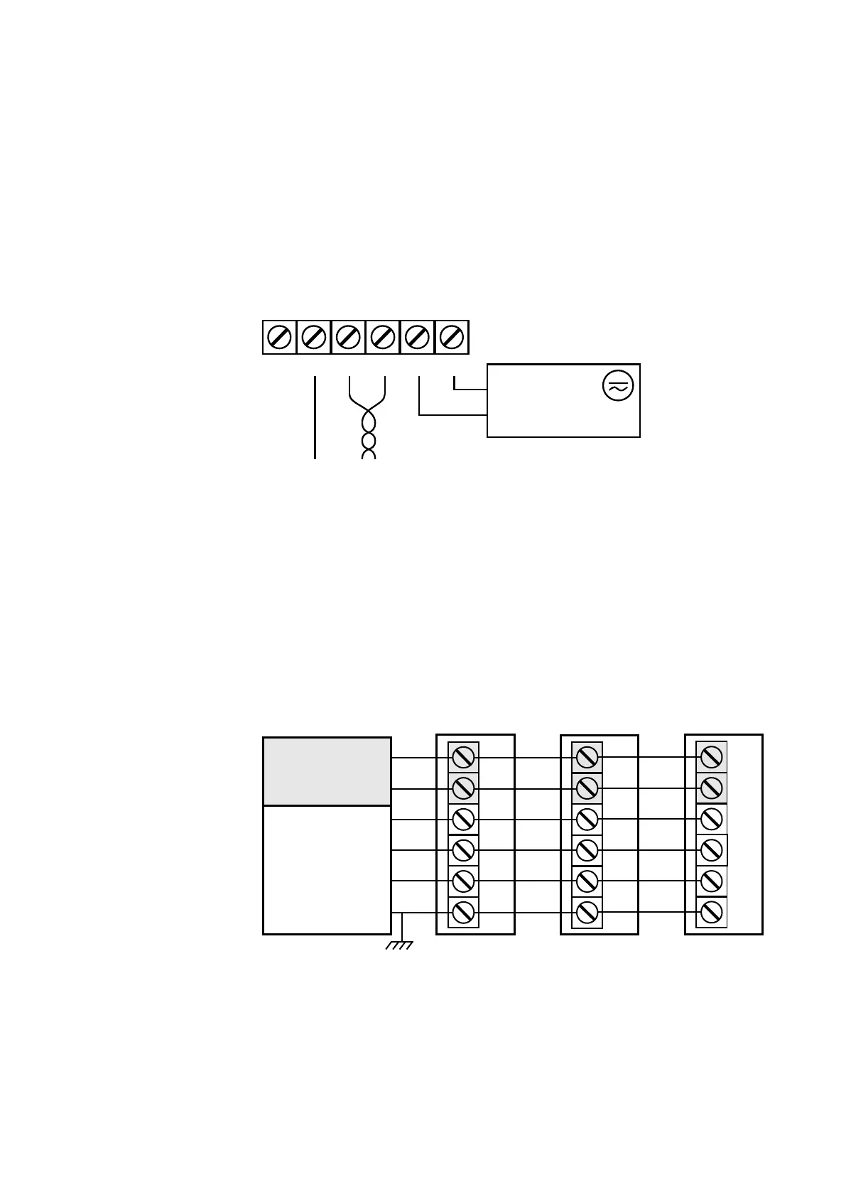
Wiring HMW95
The RS-485 line of the transmitter is isolated from the power supply. A
separate ground reference terminal (GND) is provided for the RS-485
connection.
If you are using a shielded cable, you can use the Shld terminal to hold
the exposed part of the shield. Note that the Shld terminal is floating
(not electrically connected).
1209-014
Figure 20 Wiring HMW95
Connecting Several Transmitters on Same RS-485
Line (HMW95)
Set the RS-485 termination jumper to “ON” on the transmitter that is at
the end of the line. This terminates the line with a 120 Ω resistor. For
location of the jumper, see section Transmitter Parts - Inside on page 6.
Connect the cable shield to ground on the building controller side.
1209-015
Figure 21 Several Transmitters on Same RS-485 Line
D- -VsD+ +Vs
+
-
P
o
we
r
su
pp
l
y
1
8 .
.
. 3
5 V
D
C
o
r 2
4
VA
C ±
20%
RS
-485
Sh
ld
G
ND
Transmit
te
r
D-
-Vs
D+
+Vs
Shld
GND
B
uil
ding
con
tro
ller
Tra
nsm
itt
er Transmit
t
er
Power
s
upp
ly
D-
D
+
+Vs
-
Vs
GND
SHIELD
RS-485:
B
ACnet or
MO
DBUS
mas
ter
C
onnect shield o
n contr
oller s
ide
Set RS-
485
t
ermination jump
er
D-
-V
s
D+
+Vs
Shld
GND
D-
-Vs
D+
+Vs
Shld
G
ND

 Loading...


