15A 15B
16
17
Valcom, Inc.
5614 Hollins Road
Roanoke, VA 24019
USA
P. 540-563-2000
F. 540-362-9800
www.valcom.com
Valcom, Inc.
5614 Hollins Road
Roanoke, VA 24019
USA
P. 540-563-2000
F. 540-362-9800
www.valcom.com
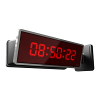
Flag Mount Installation
16) Use the M3/5-15x12 screws to attach the display board to the housing.
NOTE: For 2.5” Digit clocks, the holes for the screws will be on the left and right inner surfaces of the
housing. For 4.0” Digit Clocks, the holes will be on the top and bottom surfaces.
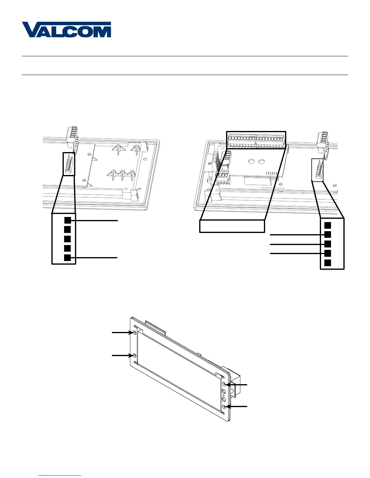
15A) If you are installing a digital clock that uses a
2-wire digital sync system, attach the wires to the
port as shown below.
15C) If you are installing a digital clock that uses
sync-wire correction, attach the wires to the
appropriate sync-wire ports. Refer to the section,
“Inputs - Clock Side - Sync Wire” for instructions
regarding each system.
1
2
3
4
5
24VDC (Orange)
24VDC (Yellow)
110VAC (Black)
110VAC (White)
Sync-Wire Ports
1
2
3
4
5
Ground (Green)