807
Thermo plus 160/230/300/350 8 Repairs
Installation
1. If necessary, install solenoid valve (6, Fig. 805) onto
the fuel pump (9) (siehe 8.9).
2. Install new O-rings (10) and a new screen insert (11)
into the fuel pump (9).
ATTENTION:
In order to avoid damage to the O-rings, to not twist
fuel pump (9) during assembly.
New screws with coated threads must be used for
installing the fuel pump.
3. Align the fuel pump (9) with the burner housing (15)
and bring it into installation position. Before doing this,
align if necessary the coupling (17) by rotating it on the
burner motor shaft.
4. Mount the fuel pump (9) using 3 new screws (12, with
coated threads) and tighten them.
5. Reconnect the solenoid valve (6) plug to the control
device (14).
6. If required, install the nozzle block preheater (see
8.10).
7. Install disc (3, Fig. 804).
8. Install electronic ignition unit (see 8.6).
8.9 Solenoid valve removal and
installation
NOTE:
The solenoid valve must be completely replaced and may
not be further dismantled! In case of replacement or
assembly and disassembly a new gasket ring must be
used.
It is not absolutely necessary to remove the fuel pump for
removal of the solenoid valve.
Make sure that any fuel leaking is immediately bound and
professionally disposed of.
Removal
1. Remove burner head (see 8.2).
2. Lift off ignition electrode (3, Fig. 805) from the electro-
nic ignition unit by twisting a screwdriver sideways
(see Fig. 804) and remove it.
3. Remove disc (5, Fig. 805).
4. Disconnect the solenoid valve plug (6) from the con-
trol device (14).
5. Using suitable tools loosen the hexagon, wrench size
16 (6, Fig. 806) of the solenoid valve (6, Fig. 805) from
the fuel pump (9) and unscrew solenoid valve (6).
Installation
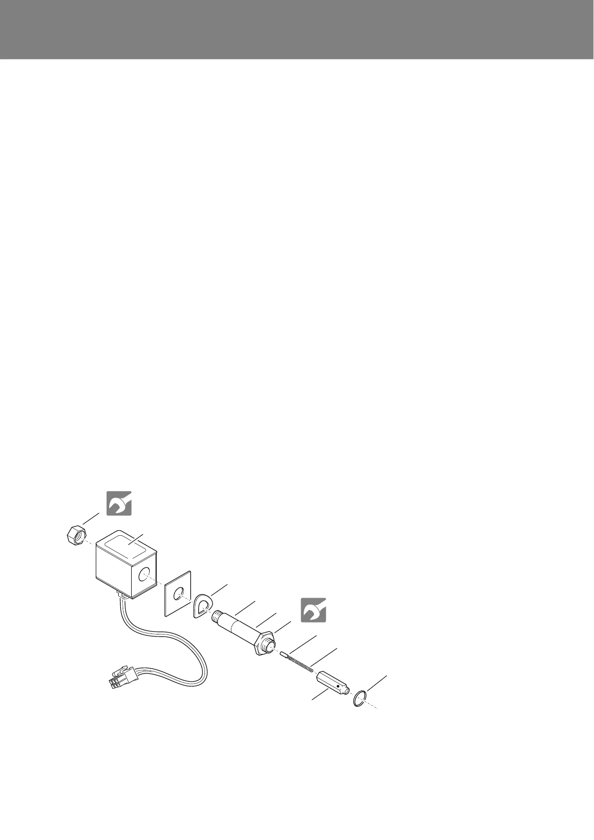
1. The gasket ring (10, Fig. 806) towards the fuel pump
must be replaced. Observe the proper installation
position of plunger, spring and tappet (see Fig. 806).
Attach the solenoid valve (6, Fig. 805) to the fuel pump
(9).
If the SW12 lock nut (1, Fig. 806) has been inadver-
tently loosened, tighten the nut to a defined degree
(2 +0.2 Nm) and then secure it using thread lock.
Fig. 806 Solenoid valve removal and installation
2
1 Nut, wrench size 12
2 Magnetic coil (coil
with cable, plug and
plate)
3 Spring washer
4 Core
5 Tube
6 Hexagon, wrench
size 16
7 Tappet
8 Spring
9 Plunger
10 Gasket ring
1
3
4
6
7
9
10
5
8
5 ±0.5 Nm
2 +0.2 Nm



 To Next Page