- 38 -
8- Service procedures- Cylinder head
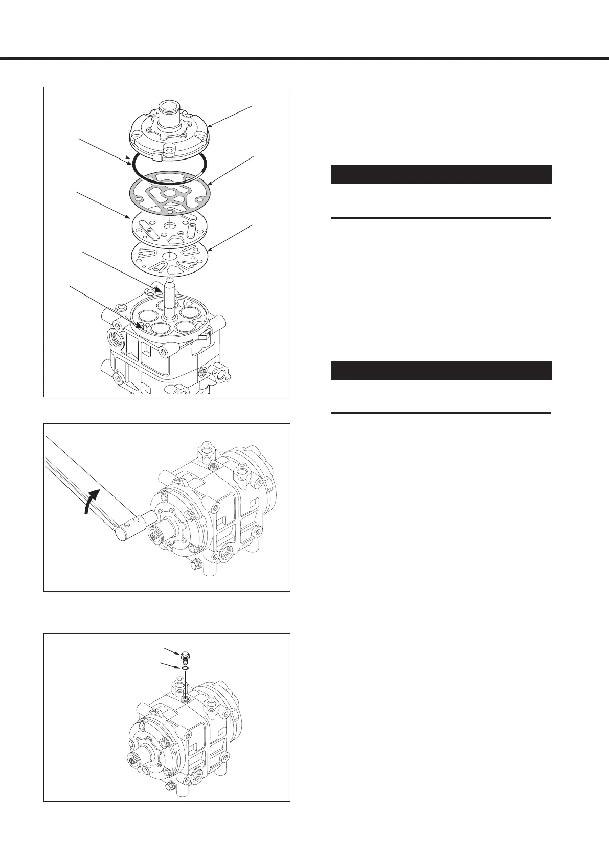
O-ring
Gasket
Valve plate
assembly
Guide
597067-6100
Front cylinder head
1. Place the cylinder shaft assembly on the
bench with the front side up.
2. Install the front suction valve so that it
matches the spring pins.
3. Install the front valve plate on the front
suction valve.
4. Coat the new gasket with clean compressor
oil and install it on the front valve plate.
5. Position the guide (597067-6100) on the
shaft.
6. Coat the new O-ring with clean compressor
oil and install it on the front cylinder head.
7. Install the front cylinder head.
8. Remove the guide (597067-6100).
9. Install the five bolts from the front cylinder
head side and tighten them to the specified
torque.
Specified torque: 25 ~ 29 N·m
{2.5 ~ 3.0 kgf·m, 18 ~ 22 lbf·ft}
Tighten each bolt gradually (in three or more
stages) to ensure the specified torque.
10. Turn the drive shaft 2 ~ 3 times by hand to
ensure that the shaft rotates smoothly.
11. Fill the compressor with the specified amount
of clean compressor oil through the oil filler.
12. Install the oil filler plug with a new O-ring,
and tighten it to the specified torque.
Specified torque: 14 ~ 16 N·m
{1.4 ~ 1.6 kgf·m, 10 ~ 12 lbf·ft}
13. Install the strainer in the suction port.
When the connectors are installed
14. Fit blanking plates to the suction and
discharge connections, and tighten it to the
specified torque.
Specified torque: 20 ~ 24 N·m
{2.0 ~ 2.4 kgf·m, 14 ~ 17 lbf·ft}
15. Install the magnetic clutch (see p. 29).
16. Run-in the compressor (see p.19).
17. Perform the leak test (see p. 20).
Ensure each valve matches each cylin-
der’s valve escape groove.
CAUTION!
Align the roll pins and tap the head
lightly and evenly with a plastic hammer.
CAUTION!
Oil filler plug
O-ring
Roll pins
Front cylinder head
Suction valve