11
© Vallox Oy - All rights reserved
INSTALLATION
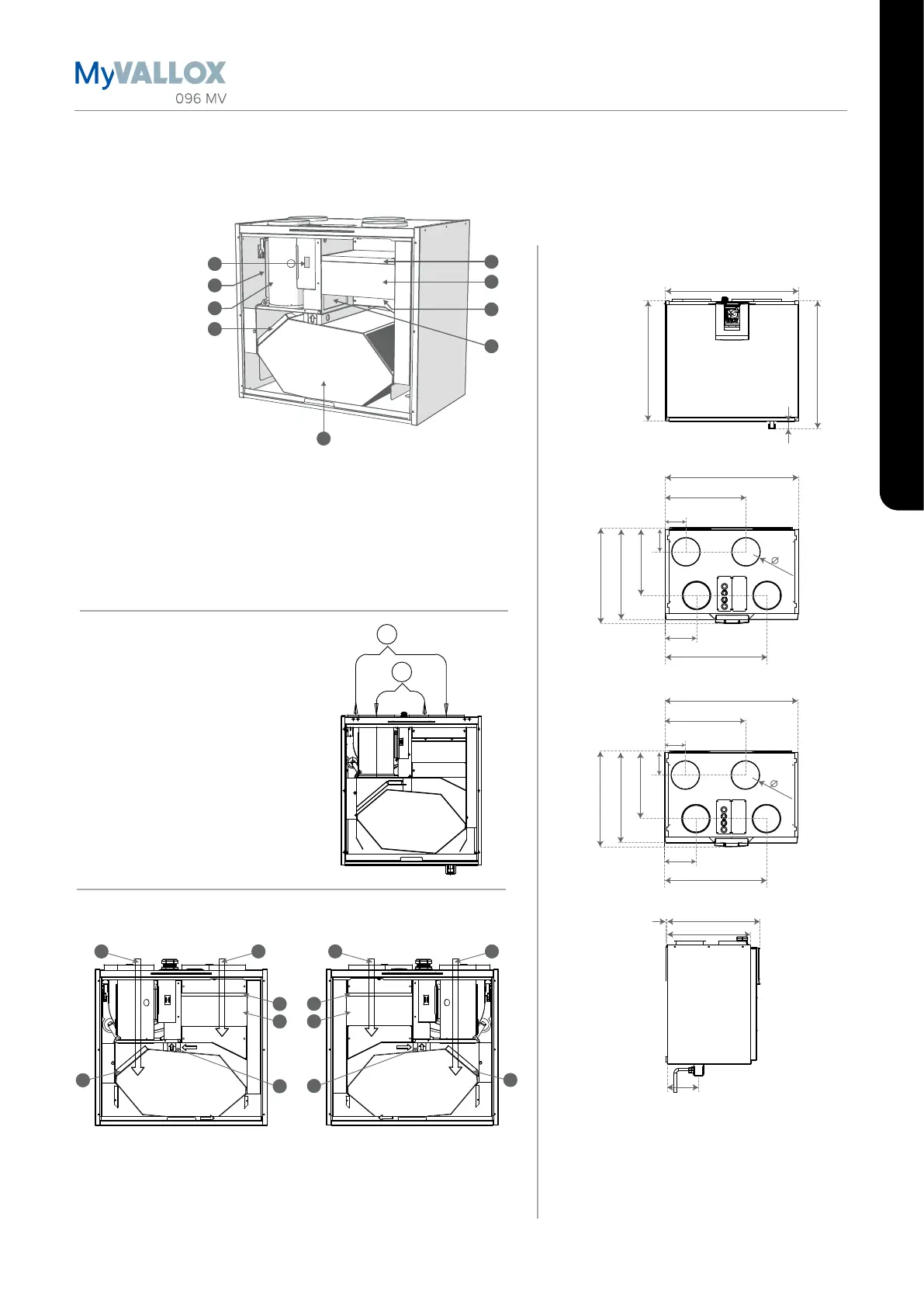
DIMENSIONS AND DUCT OUTLETS
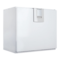
Vallox 096 MV
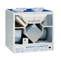
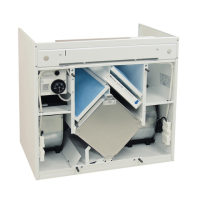
Main parts
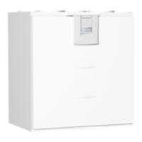
Dimensions and duct outlets
Dimensions
A
B
1
2
3
4
5
6
7
8
9
600
545
583
38
93
102
298
363
600
141
459
407
430
R
1
2
3
4
93
102
298
363
600
141
459
407
430
1
2
3
4
L
143
6
380
424
125
125
3
4
3
5
12
3
4
3
5
1 2
1. Extract air fan
(behind the protective cover)
2. Supply air fan
(behind the extract air duct)
3. Fine filter for supply air
4. Heat recovery cell
R model in the figure.
In the L model, the parts are mirrored
5. Bypass damper of the HR cell
6. Coarse filter for supply air
7. Coarse filter for extract air
8. Post-heating resistor
(behind the extract air duct
9. Safety switch
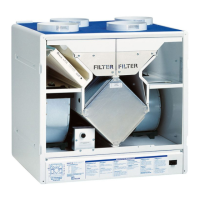
Air flow measurement points
A Supply air
B Extract air
Measurement points after the outlet
collar. The fan curves indicate the
total pressure accounted for by duct
losses.
1. Supply air
2. Extract air
3. Coarse filter
Locations of supports for HR cell
L modelR model
4. Fine filter
5. Upper support for HR cell
Duct outlets
Inner diameter of the outlet collar: 125mm
1. Supply air from the unit to the apartment
2. Extract air from the apartment to the unit
3. Exhaust air flowing outdoors from the unit
4. Outdoor air to the unit
 Loading...