27
© Vallox Oy - All rights reserved
TECHNICAL SPECIFICATIONS
S
IP
P
V
K
C
YY2
A
G
H
D
F
E
N
B
C
N
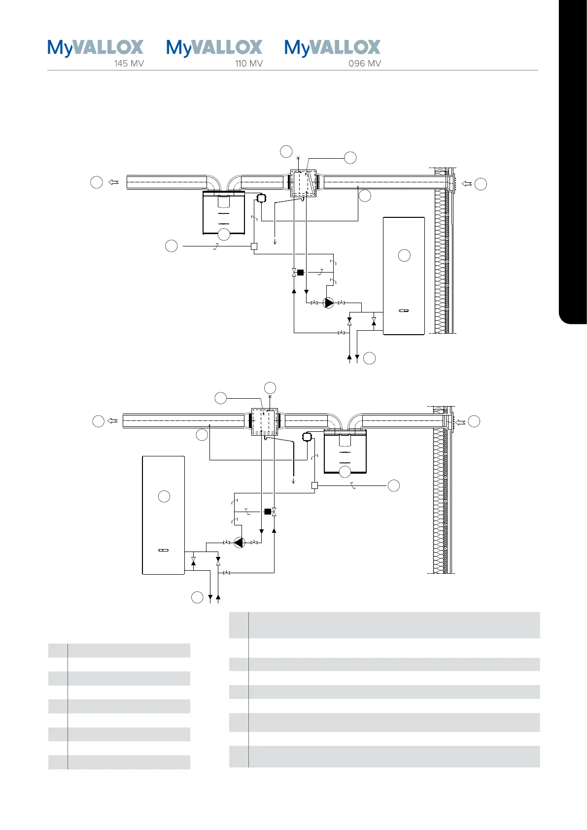
DUCT RADIATOR OPERATION CHART
A Ventilation unit
B Supply air
C Outdoor air
D Feed from the distribution board
E Air extraction
F Duct radiator (reverse connection)
G Heat pump
H Heat collection circuit
N External NTC sensor
P
Circulation pump. Not included in the delivery. The pump should be suited to pumping
liquid colder than the surrounding air, due to risk of condensation (for example, Grundfos
Magna 1 25-80).
V
Solenoid valve. Not included in the delivery. The valve that is chosen must be compatible
with the heat collection circuit fluid (for example, Danfoss 032U161431).
K Condensing water tube. Not included in the delivery.
IP De-aerator. Not included in the delivery.
S External electrical junction box for the MV
N External NTC sensor for Vallox MV ventilation units
C
24 VDC relay/contactor for controlling the pump and the solenoid valve. Not included in
the delivery. (For example, ABB CR-P024DC2)
Y One-way valve. Not included in the delivery.
Y2
One-way valve. Not included in the delivery. The pressure loss must be less than the
pressure loss of the heat pump.
In the supply air duct
IP
B
C
G
H
D
E
S
P
V
K
C
Y Y2
A
F
N
In the outdoor air duct
 Loading...