24
TECHNICAL SPECIFICATIONS
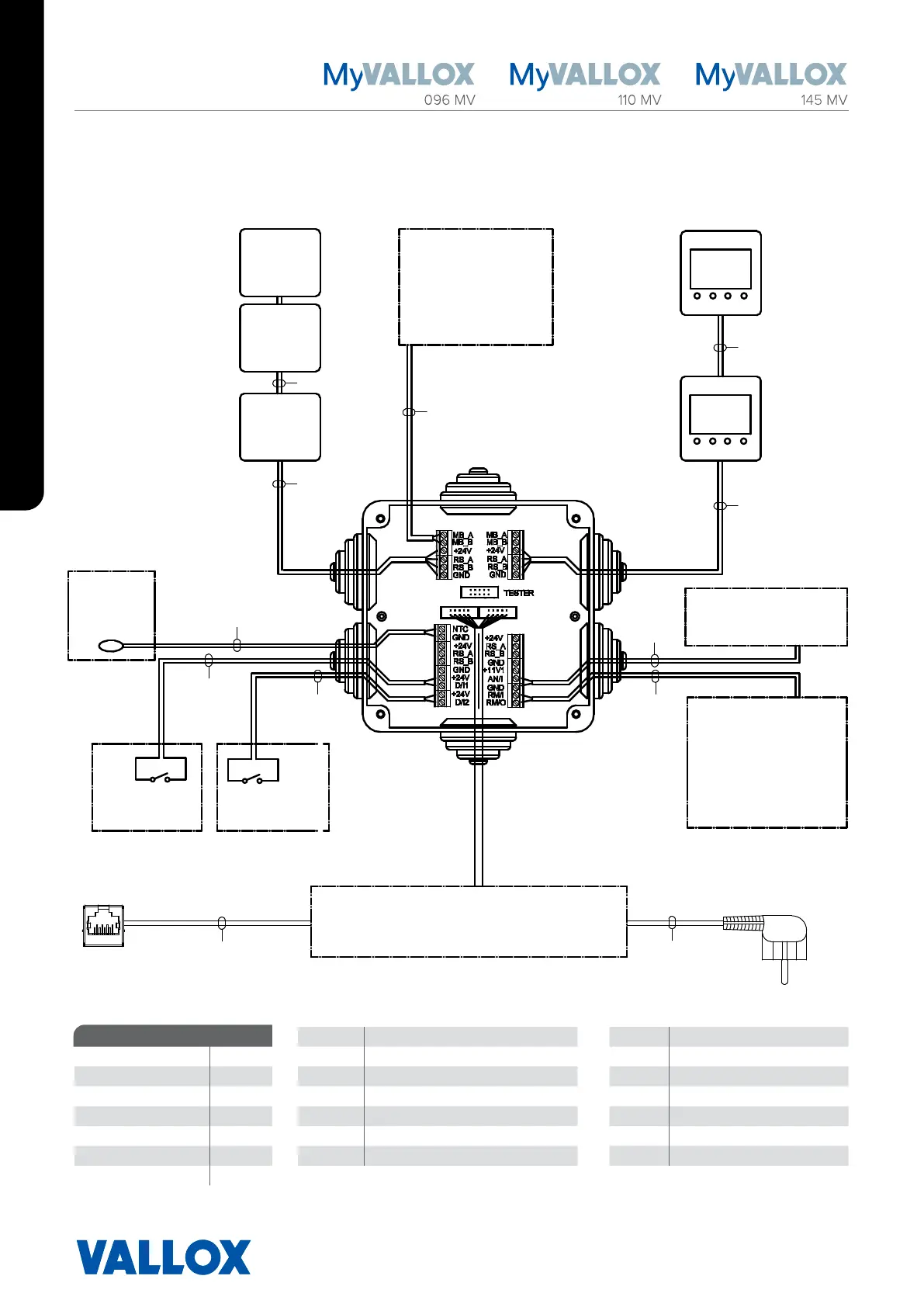
EXTERNAL ELECTRICAL CONNECTION
3x1,5S
2x2x0,5+0,5
2x0,5
2x0,5
7028350
2014-08-29 JS
2x2x0,5+0,5
2x0,5
2x2x0,5+0,5
2x2x0,5+0,5
2x2x0,5+0,5
2x0,5
2x0,5
CAT
Analog input
two dierent
functions
Potential-free contact
data 24VDC can be
programmed to display
information such as errors
or to control the valve
and pump of the MLV
radiator.
Plug connection
1.2 m on top of the unit
MyVallox
control
panel
MyVallox
control
panel
REMOTE
MONITORING
Modbus RTU
VENTILATION UNIT INTERNAL
ELECTRICAL CONNECTION
MyVallox
%RH
sensor
MyVallox
CO
2
sensor
External
temperature
sensor
NTC 4K7
Digital input 1
8 dierent
functions
Digital input 2
8 dierent
functions
Ethernet connection
on top of the unit
RJ45 female
0.3W
1.2W
1W
1W
MyVallox
VOC
sensor
2 W
MB_A External Modbus A signal D/I1 Digital input 1
Maximum ≤6W MB_B External Modbus B signal D/I2 Digital input 2
MyVallox Control 1W +24V +24V voltage (DC) 11V1 11.1 V operating voltage
MyVallox Touch 0.5 W. GND Digital and analog ground potential AN/I Analog input 0-10VDC
MyVallox %RH sensor 0.3W RS_A Local hardware Modbus A signal RM/I 24V relay input
MyVallox CO
sensor 1.2W RS_B Local hardware Modbus B signal RM/O 24V relay output
MyVallox VOC sensor 2W NTC External temperature sensor connector
Voltage 24 VDC
POWER SUPPLY
 Loading...