INSTALLATION GUIDE – 203 DISPLAY
www.valortpms.com
6
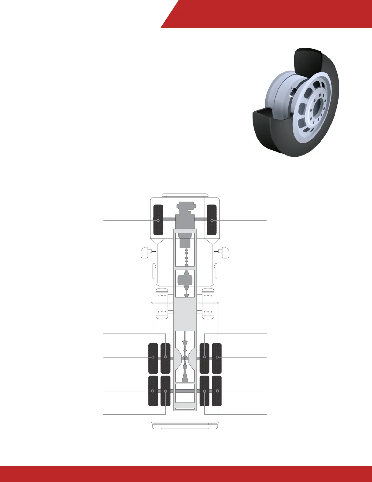
1.4 Installing TPMS Sensors
Once the ID module has been removed, attach sensor to corresponding
rim. Suggested mounting location is near the air valve. Wipe the area clean
with a cloth, remove the 3M adhesive protector and place on rim. Run steel
band through sensor bracket and tighten (max 2ft/lb). Please note, sensor
must be placed on the solid, NOT serrated portion of the band.
Suggested Tire/ID Module positioning:
Tractor (10-Wheel)
PART 1 : System Installation
1A – Axle 1 (Left)
1D – Axle 1 (Right)
2C – Axle 2 (Inner Right)
2D – Axle 2 (Outer Right)
3D – Axle 3 (Outer Right)
3C – Axle 3 (Inner Right)
2B – Axle 2 (Inner Left)
2A – Axle 2 (Outer Left)
3A – Axle 3 (Outer Left)
3B – Axle 3 (Inner Left)