19
Appendix E (cont’d)
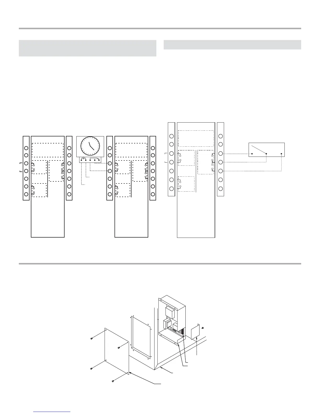
TERMINAL CONTROL DIAGRAMS
Occupancy control is achieved by connection to the terminal
interface shown below. These terminals require a dry contact which
could be provided by a number of types of controls such as a timer,
light sensor, occupancy sensor, building management system,
or other. The unit will not operate unless these contacts are
closed!!
The illustration below shows a factory installed jumper and
programmable timer option (supplied by others).
Remote fan control can be achieved by connecting dry
contact controls to the terminal interface at terminals labeled:
LOW - COM - HIGH.
These controls could be the following: SPDT switch, dehumidistat,
CO
2
sensor, light sensor, timer, building management system, etc.,
supplied by others.
The illustration below represents a switch connected to the unit.
E-3: OCCUPIED TIMER/SENSOR CONNECTION
(NOT SOLD BY VENMAR OR
VÄNEE)
JUMPER
(factory installed)
OCC. CONTROL
(field installed)
NSB Timer
1
M
2345
JUMPER
CLASS 2 VOLTAGE
NOTE:
Connections are all dry
contacts except wall
control and 24VAC power
supply.
Use of 24VAC circuit
requires isolating contacts
(ex. thermostat) to prevent
interconnection of Class 2
outputs.
WALL CONTROL
CLASS 2 VOLTAGE
Black
OCCUPIED
TIMER/
SENSOR
24 (-) VAC
F
F
LOW
COMMON
HIGH
Red
Green
Yellow
VE0314A
NOTE:
Connections are all dry
contacts except wall
control and 24VAC power
supply.
Use of 24VAC circuit
requires isolating contacts
(ex. thermostat) to prevent
interconnection of Class 2
outputs.
24 (+) VAC
WALL CONTROL
Black
OCCUPIED
TIMER/
SENSOR
F
F
LOW
COMMON
HIGH
Red
Green
Yellow
E-4: REMOTE FAN CONTROL
JUMPER
REMOTE
LOW HIGH
FAN
SWITCH
WALL CONTROL
CLASS 2 VOLTAGE
Black
OCCUPIED
TIMER/
SENSOR
F
F
LOW
COMMON
HIGH
Red
Green
Yellow
NOTE:
Connections are all dry
contacts except wall control
and 24VAC power supply.
Use of 24VAC circuit
requires isolating contacts
(ex. thermostat) to prevent
interconnection of Class 2
outputs.
VE0005A
Appendix F
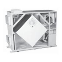
CONTROL BOX ASSEMBLY 6LC, V6LC, 12LC AND V12LC
Control cover plate
Control box
Remote control access plate
Remote wiring terminal block
Unit cabinet
VE0001A