Choose an appropriate location to install the exterior
hoods:
• There must be a minimum distance of 6’ (1.8 m)
between the hoods to avoid cross-contamination
• There must be a minimum distance of
18” (457 mm) from the ground
Make sure the intake hood is at least 6’ (1.8 m) away from
the following:
• Dryer exhaust, high efficiency furnace vent, central
vacuum vent
• Gas meter exhaust, gas barbecue grill
• Any exhaust from a combustion source
• Garbage bin and any other sources of contamination
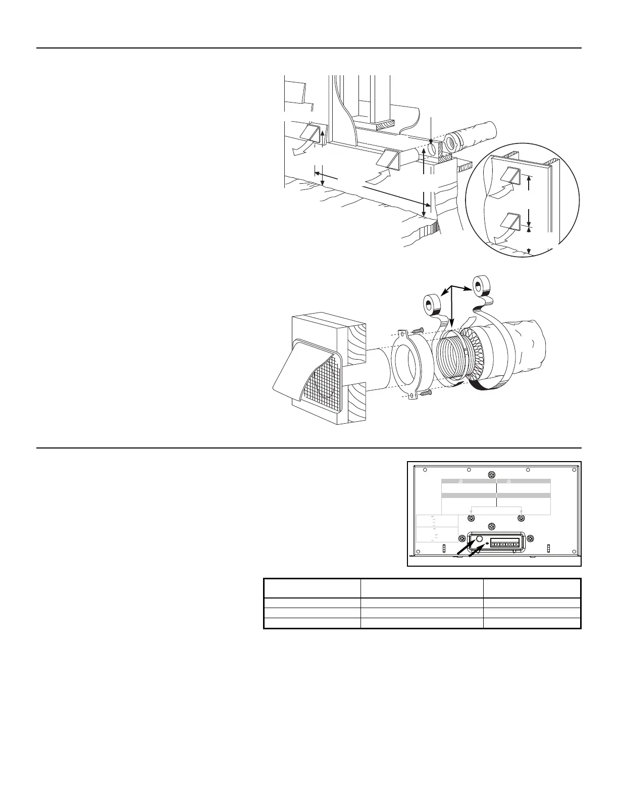
Refer to figure below for connecting insulated ducts to
the exterior hoods. An “Anti-gust intake hood” should be
installed in regions where a lot of snow is expected to fall.
All units are equipped with an integrated control, located under the unit, in front of the electrical
compartment. Use the push button (1) to control the unit. The LED (2) will then shows on
which mode the unit is in.
Refer to table beside to see how to operate the unit
using its integrated control.
TAPE AND DUCT TIE
OPTIONAL
DUCT LOCATION
EXHAUST HOOD
INTAKE HOOD
18’
(457
MM)
18”
(457
MM)
6” Ø
(152
MM)
18”
(457
MM)
6’
(1.8
M)
6’
(1.8
M)
3. CONTROLS
3.1 INTEGRATED CONTROL
If a problem occurs during the unit operation, its integrated control LED (2) will blink. The color of the blinking light depends on the type
of error detected. Refer to
Section 9 Troubleshooting
on page 17 for further details.
3.1.1 BOOT SEQUENCE
The unit boot sequence is similar to a personal computer boot sequence. Each times the unit is plugged after being unplugged, or
after a power failure, the unit will perform a 30-second booting sequence before starting to operate. During the booting sequence,
the integrated control LED will light GREEN or AMBER for 5 seconds, and then will shut off for 2 seconds. After that, the LED will
light RED for the rest of the booting sequence. During this RED light phase, the unit is checking and resetting the motorized damper
position. Once the motorized damper position completely set, the RED light turns off and the booting sequence is done.
NOTE: No command will be taken until the unit is fully booted.
PRESS ON PUSH BUTTON LED COLOR RESULTS
ONCE AMBER UNIT IS ON LOW SPEED
TWICE GREEN UNIT IS ON HIGH SPEED
THREE TIMES NO LIGHT UNIT IS OFF
WARNING
Risk of electric shock. Before performing
any maintenance or servicing, always
disconnect the unit from its power source.
AVERTISSEMENT
Danger d’électrocution. Débranchez
toujours l’appareil avant d’entreprendre
des travaux d’entretien ou de réparation.
CAUTION
Unscrew both screws to open the electrical
compartment. To completely remove, detach
from its retention wire inside.
ATTENTION
Dévisser les deux vis pour ouvrir le compartiment
électrique. Pour retirer complètement, le
détacher de son fil de rétention intérieur.
No light OFF or remote controled
Amber light LOW speed
Green ligh HIGH speed
Blinking light See User Manual
Sans lumière Arrêté ou contrôlé
par contrôle mural
Lumière ambre Basse vitesse
Lumière verte Haute vitesse
Clignotant Voir guide d’utilisation
VD0182
1
2
2. INSTALLATION (CONT’D)
2.9 INSTALLING 2 EXTERIOR HOODS
- 10 -