3. CONTROLS (CONT’D)
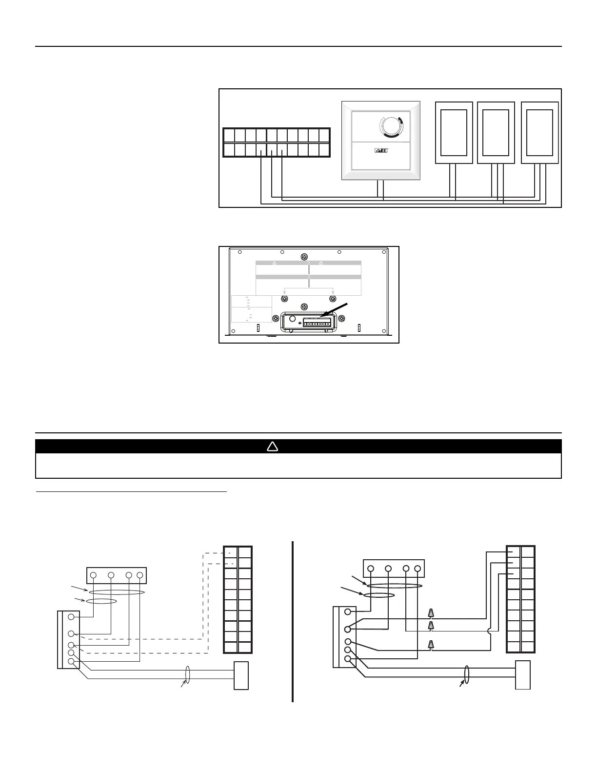
3.2.4 ELECTRICAL CONNECTION TO OPTIONAL AUXILIARY WALL CONTROLS
NOTE: If an optional auxiliary wall control is
activated and then, the Humidity
Control is being activated, this one
will override the auxiliary wall control
commands.
Once the wall control(s) connections have been made, insert the terminal connector in the bottom of the unit, on the electrical
compartment front face.
NOTE: For information about the operation of the wall controls, refer to the user guide.
WARNING
Risk of electric shock. Before performing
any maintenance or servicing, always
disconnect the unit from its power source.
AVERTISSEMENT
Danger d’électrocution. Débranchez
toujours l’appareil avant d’entreprendre
des travaux d’entretien ou de réparation.
CAUTION
Unscrew both screws to open the electrical
compartment. To completely remove, detach
from its retention wire inside.
ATTENTION
Dévisser les deux vis pour ouvrir le compartiment
électrique. Pour retirer complètement, le
détacher de son fil de rétention intérieur.
No light OFF or remote controled
Amber light LOW speed
Green ligh HIGH speed
Blinking light See User Manual
Sans lumière Arrêté ou contrôlé
par contrôle mural
Lumière ambre Basse vitesse
Lumière verte Haute vitesse
Clignotant Voir guide d’utilisation
VD0182
TERMINAL
CONNECTOR
3.2 ELECTRICAL CONNECTION TO OPTIONAL WALL CONTROLS (CONT’D)
- 12 -
4. ELECTRICAL CONNECTION TO THE FURNACE
For a furnace connected to a cooling system:
On some older thermostats, energizing the “R” and “G” terminals at the furnace has the effect of energizing “Y” at the thermostat and
thereby turning on the cooling system. If you identify this type of thermostat, you must use the ALTERNATE FURNACE INTERLOCK WIRING.
STANDARD FURNACE INTERLOCK WIRING ALTERNATE FURNACE INTERLOCK WIRING
WARNING
Never connect a 120-volt AC circuit to the terminals of the furnace interlock (standard wiring). Only use the low voltage class
2 circuit of the furnace blower control.
W R G
Y
W
R
G
C
Y
UNIT TERMINAL CONNECTOR
THERMOSTAT
TERMINALS
FOUR
WIRES
TWO WIRES
heating only
FURNACE
24-VOLT
TERMINAL BLOCK
TWO WIRES
COOLING SYSTEM
NO C NC I OC OL Y R G B
W R G Y
W
R
Y
R
G
Y
C
THERMOSTAT
TERMINAL
4 WIRES
2 WIRES
heating only
wiring
nuts
FURNACE
24-VOLT
TERMINAL BLOCK
2 WIRES
COOLING SYSTEM
NO
NC
C
UNIT TERMINAL CONNECTOR
NO C NC I OC OL Y R G B
VE0108A
NO C NC I OC OL Y R G B
20-MINUTED LIGHTED PUSH BUTTON
(5 MAXIMUM)
60-MINUTE
CRANK TIMER
HUMIDITY CONTROL
VE0105A
C
O
M
F
O
R
T
Z
O
N
E
O
F
F
%
R
E
L
A
T
I
V
E
H
U
M
I
D
I
T
Y
7
0%
60%
50%
40%
30
%
25%
20%
HUMIDITY
CONTROL
DURING FALL, WINTER
AND SPRING, SET THE
DIAL ACCORDING TO
THE DESIRED MAXIMUM
INDOOR HUMIDITY LEVEL.
DURING SUMMER SET
THE DIAL TO THE
OFF POSITION.