1. TYPICAL INSTALLATIONS (CONT’D)
1.4 ATTIC INSTALLATION FOR ERV UNITS ONLY
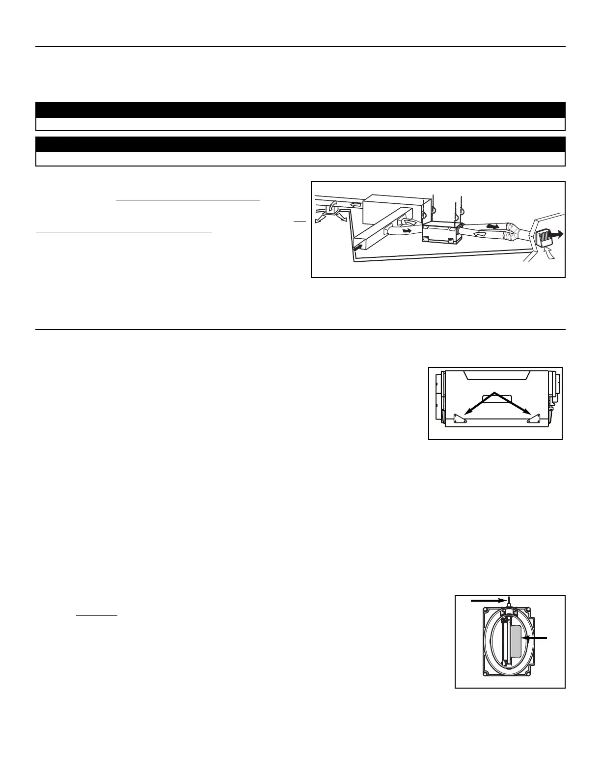
All 3 types of installations can be used in the attic (Fully ducted system, Central Draw Point or Simplified). The example shown below is
a Simplified installation (connection to a forced air system).
Stale air is exhausted to the outside. Fresh air from outside is filtered
and supplied to the return (plenum) of the forced air unit
. See figure
at right.
To avoid cross-contamination and achieve the highest efficiencies, the
forced air system blower must always be ON.
NOTE: Home with multiple forced air systems should have 1 unit on
each system.
Due to the potential temperature difference between the attic and the rest of the house, all unit ducts must be insulated.
CAUTION
The attic temperature must always be above 0°C (32°F).
CAUTION
- 5 -
2. INSTALLATION
2
.1 INSPECT THE CONTENTS OF THE BOX
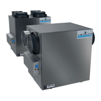
• Inspect the exterior of the unit for shipping damage. Ensure that there is no damage to the door, door latches, power cord, etc.
• Remove and discard the 2 transport brackets (A) and open the door. Discard the styrofoam
fillers (ERV units only) and remove the hardware kit from the unit. Inspect the interior of the unit
for damage. Ensure that heat or energy recovery core, core filters, insulation, dampers, etc. are
all intact.
2.2 LOCATING THE UNIT
Choose an appropriate location for the unit.
• Within an area of the house where the ambient temperature is between 10°C (50°F) and 65°C (149°F) (basement, furnace room,
closet, etc.).
• So as to provide easy access to the interior of the unit, for maintenance.
• Close to an exterior wall, so as to limit the length of the insulated flexible duct to and from the unit.
• Away from hot chimneys and other fire hazards.
• Allow for a power source (standard 3-prong grounding outlet).
• For HRV units ONLY: Close to a drain. If no drain is close by, use a pail to collect run-off.
2.3 UNIT PREPARATION
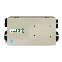
Both HRV and ERV units are equipped with 2 ports having integrated balancing damper. Turn the thumb
screw (A) clockwise to manually open and adjust the damper (B).
HRV
UNITS: Set the Fresh air to building port to wide open position, and adjust the Exhaust air to outside
port to 3rd notch.
NOTE: If the unit need to be balanced, adjust the damper of the Exhaust air to outside port to wide open
position. See
Section 6
.
ERV
UNITS: Set both Fresh air to building port and Exhaust air to outside port to wide open position.