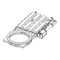
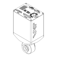
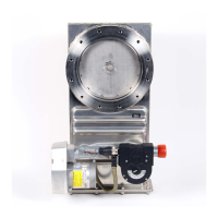
This document describes the installation, operation, and maintenance of the VAT Series 191/192 Large HV/UHV gate valve with a double-acting pneumatic actuator, designed for DN 900-1250 mm (I.D. 36"-50") applications.
Function Description
The valve utilizes VATLOCK sealing technology, which ensures mechanical locking in the closed position. When open, the mechanism is unlocked. Leaf springs hold the gate and counter plate against the carriage with ball retainers, with ball pairs situated in detents.
For closing, the mechanism moves forward into the closing position. Locking initiates once the leaf spring stop contacts the body. The ball retainers then move the ball pairs out of the detents, causing the gate and counter plate to spread apart. This action presses the gate seal against the sealing surface without scuffing. The arrangement of the ball pairs enhances the sealing force when vacuum is present on either side of the gate. The opening process reverses these movements.
The valve is primarily opened and closed pneumatically. It is designed for clean and dry vacuum applications.
Important Technical Specifications
The manual provides ordering numbers for specific product configurations:
- 19159-.E14/24/34/44
- 19160-.E14/24/34/44
- 19162-.E14/24/34/44
- 19259-.E14/24/34/44
- 19260-.E14/24/34/44
- 19262-.E14/24/34/44
Admissible Forces and Bending Moments:
Forces from system evacuation, weight of other components, or baking can deform the valve body and cause malfunction. Stress must be relieved by suitable means. The following forces and bending moments are admissible for different nominal inner diameters (DN):
| DN (nom. I.D.) |
Axial tensile or compressive force «FA» |
Bending moment «M» |
| mm |
inch |
N |
| 900 |
36 |
9800 |
| 1000 |
40 |
9800 |
| 1250 |
50 |
9800 |
If a combination of both axial forces («FA») and bending moments («M») occurs, these values are invalid, and VAT should be contacted for more information.
Compressed Air Connection:
- Requires clean, dry, or slightly oiled air.
- Admissible air pressure range is specified in the product data sheet.
- Compressed air should only be connected when the valve is installed in the vacuum system and moving parts cannot be touched.
Electrical Connection:
- Solenoid valve and position indicator connections are detailed in the product data sheet and dimensional drawing.
- Electrical components must be supplied with the correct voltage to prevent damage.
Operation under Increased Temperature:
- Maximum allowed temperature is specified in the product data sheet.
Behavior in case of Compressed Air Pressure Drop and Power Failure:
- Specific behavior details are provided in the product data sheet.
Usage Features
Installation:
- Unpacking: The valve is heavy and requires a crane for lifting. It should be lifted using five M30 eyebolt threads. Before installation, ensure the valve is in the closed and locked position. Air must be released from the cylinder by opening the air valve fitting (Pos. 73) as it is under pressure for transport protection.
- Mounting:
- Remove protective covers from body flanges.
- Clean sealing surfaces and seals of both flanges.
- Lift the valve to the mounting position using only the load rings.
- Mount the four screws evenly in a crosswise order until the seal touches the sealing surface.
- Tighten all screws with the torques appropriate for their property classes.
- Safety: Personnel must be qualified. Avoid contamination by wearing cleanroom gloves. Do not use sharp-edged tools on sealing surfaces. Use correct tightening torque and only VAT-recommended screws to prevent deformation or malfunction. Do not connect electrical power or compressed air before the product is fully mounted in the system to avoid injury from movable parts.
Manual Emergency Operation:
- Standard Solenoid Valve:
- To close: Turn the slotted screw (1) counter-clockwise to its stop.
- To open: Turn the slotted screw (1) clockwise to its stop.
- For remote operation, ensure the slotted screw is turned counter-clockwise to its stop.
- Impulse Solenoid Valve:
- To close: Turn the slotted screw (3) (coil CLOSE) clockwise to its stop. Once closed, return the screw to its original position.
- To open: Turn the slotted screw (2) (coil OPEN) clockwise to its stop. Once open, return the screw to its original position.
- For remote operation, ensure both slotted screws are turned counter-clockwise to their stop (original position).
- Safety: Keep human body parts away from movable parts during manual emergency operation.
Maintenance Features
Maintenance Intervals:
- Under clean operating conditions, the valve requires no maintenance for 10,000 cycles. After this, VAT recommends replacing the mechanism unit.
- For general overhaul or further information, contact VAT service centers.
Required Tools:
- Torque wrench
- Cleanroom wiper soaked with alcohol (2% methyl ethyl ketone)
Replacement of Valve Gate / Mechanism Unit:
- Vent chambers on both sides to atmospheric pressure.
- Open the valve.
- Disconnect compressed air supply.
- Disconnect electrical power supply.
- Remove screws (3) from the body cover (7) in a crosswise order.
- Carefully lift the actuator/mechanism unit from the body without touching the body wall. Avoid touching the actuator with lifting ropes.
- Clean the mechanism unit with alcohol if it is out of the valve body.
- If the plate seal at the mechanism unit and the bonnet seal (4) are undamaged, clean them with a cleanroom wiper. Do not clean the sealing with alcohol; for O-ring sealing, treat with a small amount of vacuum grease.
- Lift the actuator/mechanism unit back into the valve body.
- Tighten screws (3) from the body cover (7) according to the sealing technology with the correct tightening torque.
- Connect electrical power supply.
- Connect compressed air supply.
- Close the valve.
Repairs:
- Repairs should only be carried out by VAT service staff. Customers may perform repairs only with prior consent from VAT.
Dismounting and Storage:
- Dismounting: Close the valve before dismounting from the system. Follow installation steps in reverse order, observing all safety instructions.
- Storage:
- Clean/decontaminate the valve.
- Cover all valve openings with a protective foil.
- Pack the valve appropriately using original packaging material.
- Storage Conditions: Store at 10-70% relative humidity and +10°C to +50°C in a non-condensing environment.
- Packaging: Use original packaging material to prevent damage.
Packaging and Transport:
- Packaging: Ensure the valve is closed before packaging. Cover all openings with protective foil and use original packaging.
- Returning Products to VAT: Fill out the VAT form "Declaration of Chemical Contamination" and send it in advance. For radioactively contaminated products, fill out the "Contamination and Radiation Report." Contaminated products sent to VAT will be decontaminated at the customer's expense.
Disposal:
- Discard products and parts according to local regulations, especially if harmful substances are present.
Spare Parts:
- Only original VAT spare parts should be used to prevent damage.
- When ordering, specify the product's fabrication number.
- The manual lists customer-replaceable spare parts:
- Seal kit (on request, 1 per valve)
- Gate seal (on request, 1 per valve)
- Bonnet flange seal (on request, 1 per valve)
- For other spare parts, contact VAT service centers.