EasyManua.ls Logo

VAT 613 Series User Manual

VAT 613 Series
149 pages
To Next Page IconTo Next Page
Page #1 background imageLoading...
Page #1 background image
Installation, Operating &
Maintenance Instructions
984360EC.DOCX Edition 2022-08-12
Butterfly Pressure Control Valve
with RS232 interface
Series 613
DN 25-320 mm (I.D. 1“ - 12")
This manual is valid for the valve ordering number(s):
613 . . - . .GH - . . . . (2 sensor inputs / analog outputs)
613 . . - . .AH - . . . . (2 sensor inputs / analog outputs / ±15V SPS)
613 . . - . .HH - . . . . (2 sensor inputs / analog outputs / PFO)
613 . . - . .CH - . . . . (2 sensor inputs / analog outputs / ±15V SPS / PFO)
SPS = Sensor Power Supply PFO = Power Failure Option
configured with firmware : F01.0C.28.xx
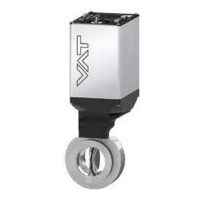
Sample picture
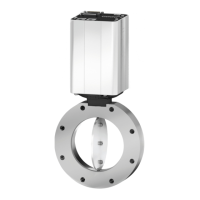
Table of Contents

Questions and Answers:

VAT 613 Series Specifications

General IconGeneral
Power supply24 VDC
Operating temperature-20°C to +70°C
Storage temperature-40°C to +85°C
Dimensions72 x 72 x 77 mm
Protection ClassIP20
Communication interfaceRS-485
Current consumption100 mA
Power Consumption2.4 W
Relative Humidity5% to 95% RH, non-condensing
Weight200 g

Summary

Description of product

Identification of product

Describes how to identify the valve's fabrication and order numbers using the identification plate.

Firmware

Instructions on how to find the firmware version via CPA or the display at start-up.

Use of product

Details the butterfly control valve's intended use in vacuum systems for clean, dry applications.

Used abbreviations

Lists and defines abbreviations used throughout the manual, such as CPA, PFO, SFS, SPS, ADC.

Related documents

Lists related documents for the product, including Product Data Sheet and Dimensional Drawing.

Important information

Highlights important statements requiring particular attention, indicated by a specific symbol.

Technical data

Refers to the product data sheet for detailed technical specifications of the control and actuating unit.

Safety

Compulsory reading material

Emphasizes the importance of reading and understanding this chapter for personal safety before any work.

Danger levels

Defines danger levels (Danger, Warning, Caution, Notice) with associated risk indicators and consequences.

Personnel qualifications

States that only qualified personnel are allowed to perform work on the product due to potential injury risks.

Safety labels

Details the safety labels used on the valve, including label identification and location on the valve.

Design and Function

Design

Provides a diagram illustrating the design components of the butterfly pressure control valve.

Function

Explains the function of the valve plate as a throttling element and the role of the integrated controller.

Installation

Initial procedure

Outlines the initial steps for installation, including unpacking, electrical setup, and configuration.

Unpacking

Provides instructions and notices for safely unpacking the valve and its components.

Installation into the system

Details the process of installing the valve into the vacuum system with important warnings and notices.

Connection overview

Presents a schematic of the controller's connection overview and system components.

Power-, Ground- and Sensor Connection

Provides guidance on connecting power, ground, and sensor cables, including cable recommendations.

Power Up

Describes the procedure after powering up the valve, noting the necessity of homing.

Power Down, Power Failure Option

Explains power down behavior and the function of the Power Fail Option (PFO).

Service Port, CPA software

Details the use of the service port and the Control Performance Analyzer (CPA) software for local operation.

Display Information

Explains the 4-digit display on the controller and how it shows configuration, status, and position information.

System Settings and States

Covers system settings and states, including identification, configuration, firmware, hardware, and statistics.

Valve Settings and States

Details valve settings and states, including actual position, states, homing, and cycle counters.

Interface RS232/485

Describes the RS232/RS485 serial communication method, operation modes, and configurations.

Pressure Sensor

Covers pressure sensor mechanical connection requirements and configuration settings.

Power Connector Digital IO

Explains the digital inputs and outputs on the power connector, including schematics and configuration.

Operation

Access Mode

Defines the valve's access mode (Local, Remote, Locked) and how to switch between them.

Control Mode

Explains the valve's state machine and how to change or read the control mode.

Pressure Control

Details the pressure control system, including controller units and control algorithms like Adaptive, PI, Softpump.

Position Control

Covers position control parameters, including actual and target position, speed, and position ramps.

Operation under increased temperature

Provides precautions for operating the valve under increased temperature conditions, including hot valves and O-rings.

Trouble shooting

Warnings

Lists warnings that indicate potential issues but do not interrupt valve operation, with their descriptions.

Errors

Describes how to handle errors, including information on error bitmap, number, code, and recovery procedures.

Troubleshooting List

Provides a comprehensive list of common failures, their checks, and corresponding actions to resolve them.

Maintenance

Maintenance intervals

Explains that the valve requires no maintenance under clean conditions but may need more frequent service if contaminated.

Maintenance procedures

Details procedures for replacing shaft feedthrough seals and the option board, with preventive maintenance recommendations.

Repairs

FPR Service

Describes the Fixed Price Refurbishment (FPR) service for products and components offered by VAT.

Dismounting and Storage

Dismounting

Provides instructions for dismounting the valve, emphasizing contamination control and valve position.

Storage

Gives guidelines for proper storage, including environmental conditions and packaging to prevent damage.

Packaging and Transport

Packaging

Details the proper packaging procedure for the valve, including closing the valve and using protective foil.

Transport

Provides a notice regarding inappropriate packaging and VAT's disclaimer for resulting damages.

Disposal

Spare parts

ISO-KF for DN 25 – 50 mm

Lists ISO-KF spare parts for valve units, including aluminum and stainless steel options without heating.

ISO-F for DN 63 – 320 mm

Provides a list of ISO-F spare parts for valve units, including aluminum and stainless steel options without heating.

Control unit and Accessories

Lists part numbers for control units, accessories like power supply units, cables, and centering rings with O-rings.

Related product manuals