EasyManua.ls Logo

VAT 642 Series - User Manual

Default Icon
119 pages
Print Icon
To Next Page IconTo Next Page
Loading...
Installation, Operating &
Maintenance Instructions
742280ED Edition 2017-11-24
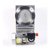
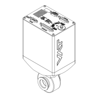
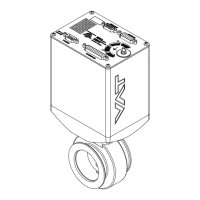
Control gate valve
with RS232 interface
Series 642
DN 63- 400 mm (I.D. 2.5“ - 16")
This manual is valid for the valve ordering number(s):
642 . . - . .TG - . . . . (Master / 1 sensor input)
642 . . - . .TH - . . . . (Master / 2 sensor inputs)
642 . . - . .VG - . . . . (Master / 1 sensor input / ±15V SPS)
642 . . - . .VH - . . . . (Master / 2 sensor inputs / ±15V SPS)
642 . . - . .UG - . . . . (Master / 1 sensor input / PFO)
642 . . - . .UH - . . . . (Master / 2 sensor inputs / PFO)
642 . . - . .WG - . . . . (Master / 1 sensor input / ±15V SPS / PFO)
642 . . - . .WH - . . . . (Master / 2 sensor inputs / ±15V SPS / PFO)
642 . . - . .TV - . . . . (Master / 1 sensor input / analog outputs)
642 . . - . .TW - . . . . (Master / 2 sensor inputs / analog outputs)
642 . . - . .VV - . . . . (Master / 1 sensor input / analog outputs / ±15V SPS)
642 . . - . .VW - . . . . (Master / 2 sensor inputs / analog outputs / ±15V SPS)
642 . . - . .UV - . . . . (Master / 1 sensor input / analog outputs / PFO)
642 . . - . .UW - . . . . (Master / 2 sensor inputs / analog outputs / PFO)
642 . . - . .WV - . . . . (Master / 1 sensor input / analog outputs / ±15V SPS / PFO)
642 . . - . .WW - . . . . (Master / 2 sensor inputs / analog outputs / ±15V SPS / PFO)
642 . . - . . GS - . . . . (Slave)
642 . . - . . HS - . . . . (Slave / PFO)
SPS = Sensor Power Supply PFO = Power Failure Option
Master configured with firmware: 600P.1G.00.07…08
Slave configured with firmware: 600P.1G.00.07…08
Sample picture

Table of Contents

Other manuals for VAT 642 Series

Questions and Answers

  • R
    Ruth FergusonSep 3, 2025
    Why is pressure not ‘0’ after ZERO on VAT Control Unit?
    • B
      Brian BentonSep 3, 2025
      If the pressure is not ‘0’ after performing ZERO on your VAT Control Unit, it could be due to: * Sensor voltage shifting. Wait until the sensor stabilizes before performing ZERO. * The system not being pumped to base pressure. OPEN VALVE and bring the chamber to base pressure before performing ZERO. * The sensor offset voltage exceeding ±1.4V. Replace the pressure gauge.
  • A
    Amber BruceAug 25, 2025
    Why does the VAT Control Unit display show «E 22» (fatal error - rotation angle of valve plate limited during operation)?
    • J
      Jonathan WoodsAug 25, 2025
      The error «E 22» indicates that the rotation angle of the valve plate is limited during operation, possibly due to a heavily contaminated valve unit or a mechanical obstruction. Clean the valve unit or resolve the obstruction. You may also try resetting the control unit by cycling the power OFF and then ON, or by sending a reset command locally via the service port with CV/CPA/Service Box2.
  • E
    Erika PerezDec 1, 2025
    How to resolve VAT 642 PRESSURE CONTROL not optimal?
    • C
      christine49Dec 1, 2025
      If the PRESSURE CONTROL on your VAT Control Unit is not optimal, consider these potential causes and solutions: * Ensure that the «Setup procedure» is performed completely. * Perform LEARN. Refer to «LEARN» for details. * Perform ZERO before repeating LEARN. Refer to «Setup procedure» for details. * If LEARN was interrupted, repeat it. Refer to «LEARN» for details. * Ensure stable gas flow during LEARN and repeat LEARN if necessary. Refer to «LEARN» for details. * Tune the valve for your specific application. Refer to «Tuning of control performance» for details. * Verify that the sensor range is suitable for the application; the controlled pressure should be >3% and < 98% of the sensor's full scale. * Ensure a shielded sensor cable is used to minimize noise on the sensor s...
  • S
    Stacy RodriguezSep 9, 2025
    Why does VAT Control Unit remote operation not work?
    • G
      Gina KnappSep 9, 2025
      Remote operation of the VAT Control Unit might not work because local operation via the service port is active, or the safety mode is active (check for 'D' on the display). To resolve this, switch to remote operation and ensure the motor is powered. Refer to «Electrical connection» for details.
  • J
    John RamirezSep 15, 2025
    What to do if the VAT 642 Control Unit display shows 'D 0' Motor Interlock is open?
    • B
      brian66Sep 15, 2025
      If the display shows 'D 0', it means the motor interlock is open. Ensure that power is supplied to the motor. For details, refer to «Electrical connection».
  • J
    Jason FloydSep 6, 2025
    Why is the pressure reading wrong or negative on my VAT Control Unit?
    • M
      Mary WattsSep 6, 2025
      If the pressure reading on your VAT Control Unit is wrong or negative, check the sensor connections as described in «Electrical connection». Verify if a 2 sensor version is present at the valve controller and verify the configuration. Refer to «Setup procedure». Perform ZERO when base pressure is reached. Refer to «ZERO» for details. Also, verify the sensor supply voltage.
  • B
    brandy55Aug 31, 2025
    What to do if CLOSE VALVE does not work on VAT Control Unit?
    • R
      Rebecca MortonAug 31, 2025
      If the CLOSE VALVE function is not working on your VAT Control Unit: * Check if safety mode is active (indicated by 'D' on the display) or if maintenance mode is active. Provide power to the motor to allow for operation. * Refer to «Electrical connection» for details. * Also, refer to the section for “Display shows «M C»” in this table.
  • L
    Lindsey PerkinsSep 18, 2025
    What to do if pressure is not ‘0’ after ZERO PRESSURE CONTROL on VAT 642?
    • D
      Danielle HornSep 18, 2025
      If the pressure is not '0' after performing ZERO PRESSURE CONTROL, it could be due to sensor voltage shifting; wait until the sensor stabilizes before performing ZERO. Ensure the system is pumped to base pressure; open the valve and bring the chamber to base pressure before performing ZERO. If the sensor offset voltage exceeds ±1.4V, replace the pressure gauge. Check if safety mode is active, indicated by a 'D' on the display, and provide power to the motor if necessary. Refer to «Electrical connection» for details if PRESSURE CONTROL is selected, indicated by a 'P' on the display. Ensure that LEARN has been performed.
  • J
    James WarrenSep 12, 2025
    Why VAT 642 Control Unit OPEN VALVE does not work?
    • K
      Kaitlin MartinezSep 12, 2025
      The VAT Control Unit OPEN VALVE function may not work if the safety mode is active (check for 'D' on the display) or if the maintenance mode is active. Provide power to the motor and refer to «Electrical connection» for details. Also, refer to “Display shows «M100»” in this table.
  • F
    fischertimothyAug 27, 2025
    What does it mean when VAT 642 display shows «D 0» Motor Interlock is open?
    • S
      Shane MossAug 27, 2025
      If the display shows «D 0», it means the Motor Interlock is open. Ensure the motor is receiving power. Refer to «Electrical connection» for details.

VAT 642 Series Specifications

General IconGeneral
BrandVAT
Model642 Series
CategoryControl Unit
LanguageEnglish

Related product manuals