EasyManua.ls Logo

VAT 615 Series - User Manual

VAT 615 Series
102 pages
Print Icon
To Next Page IconTo Next Page
Loading...
Installation, Operating & Maintenance Instructions
Series 615 DN 40 (I.D. 1½”), DeviceNet
VAT Vakuumventile AG, CH-9469 Haag, Switzerland
Tel +41 81 771 61 61 Fax +41 81 771 48 30 CH@vatvalve.com www.vatvalve.com
603476EA
2013-07-25
1/102
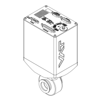
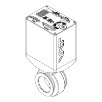
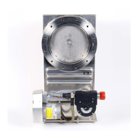
Butterfly control & isolation valve
with extended control range
with DeviceNet interface
sample picture
This manual is valid for the valve ordering number(s):
61532-KEAQ-0001
configured with firmware 615P.1F.08 and 502689 (DeviceNet
®
)
The fabrication number is indicated on each product as per the label
below (or similar):
Fabrication No.:
615 . . . . . . . . . . / . . . .
A . . . . . .
Fabrication number
Explanation of symbols:
Read declaration carefully before you start any other
action!
Keep body parts and objects away from the valve
opening!
Attention!
Hot surfaces; do not touch!
Loaded springs and/or air cushions are potential
hazards!
Wear gloves!
Disconnect electrical power and compressed air lines.
Do not touch parts under voltage!
Read these «Installation, Operating & Maintenance Instructions» and the enclosed «General
Safety Instructions» carefully before you start any other action!

Table of Contents

Questions and Answers

  • T
    thomasyoungSep 9, 2025
    What does it mean when my VAT 615 display shows «E 40» (fatal error - motor driver failure detected)?
    • M
      Morgan SheppardSep 9, 2025
      If your VAT Control Unit displays «E 40», it indicates a fatal error: a motor driver failure has been detected. Replace the control and actuating unit.
  • L
    Luis JohnsonAug 25, 2025
    Why is the VAT Control Unit pressure reading wrong or negative?
    • J
      John MarshallAug 25, 2025
      A wrong or negative pressure reading may occur if the sensor(s) are not connected, a 2 sensor version is present at the valve controller, ZERO hasn't been done, or the sensor power supply doesn't provide enough power for the sensor(s). Ensure the sensor(s) are properly connected, verify the valve version and configuration, perform ZERO when base pressure is reached, and verify the sensor supply voltage.
  • K
    Kenneth HamptonAug 25, 2025
    What to do if VAT Control Unit PRESSURE CONTROL does not work?
    • K
      Kristin DyerAug 26, 2025
      If the PRESSURE CONTROL does not work, it might be because the safety mode is active, PRESSURE CONTROL is not selected, or LEARN hasn't been done. Provide power to the motor, select PRESSURE CONTROL mode, and perform LEARN.
  • S
    Stephanie StrongSep 23, 2025
    Why is the PRESSURE CONTROL not optimal on my VAT Control Unit?
    • C
      christopherhernandezSep 23, 2025
      To address suboptimal PRESSURE CONTROL on your VAT Control Unit: 1. Completely perform the «Setup procedure». 2. Perform LEARN, referring to «LEARN» for details. 3. Perform ZERO, then repeat LEARN, consulting «Setup procedure» for details. 4. Repeat LEARN, referring to «LEARN» for details, ensuring stable gas flow. 5. Tune the valve for your application, referring to «Tuning of control performance» for details. 6. Use a sensor with a suitable range (controlled pressure should be >3% and < 98% of the sensor's full scale). 7. Ensure a shielded sensor cable is used.
  • M
    Mr. Richard Mcdonald MDSep 10, 2025
    What should I do if my VAT Control Unit's Network Status LED is flashing red (time out)?
    • K
      Kristin BrownSep 10, 2025
      If the Network Status LED on your VAT Control Unit is flashing red, it indicates a timeout. This means the I/O connections are in a timeout state. Reestablish the I/O connections to resolve this.
  • J
    Jason AndrewsSep 14, 2025
    Why does remote operation not work on my VAT Control Unit?
    • S
      susanortizSep 15, 2025
      To address remote operation issues with the VAT Control Unit, ensure you switch to remote operation mode. Also, verify that the motor is receiving power. Refer to the «Electrical connection» section for detailed instructions.
  • K
    Kevin MoodySep 4, 2025
    How to fix VAT 615 when remote operation (DeviceNet®) does not work?
    • R
      Ronald BellSep 4, 2025
      If remote operation isn't working on your VAT Control Unit, it might be because local operation via the service port is active, indicated by a 'D' on the display. Switch to remote operation and ensure power is supplied to the motor to allow for operation.
  • M
    Michael LeeSep 4, 2025
    What does it mean when my VAT 615 Control Unit display shows «E 22» (fatal error - rotation angle of valve plate limited during operation)?
    • J
      Jeffrey BerrySep 4, 2025
      If your VAT Control Unit displays «E 22», it means there's a fatal error because the rotation angle of the valve plate is limited during operation. This is possibly due to a heavily contaminated valve unit or a mechanical obstruction of the valve plate. Clean the valve unit and resolve any obstructions to fix this.
  • M
    Michelle SmithSep 23, 2025
    What to do if pressure is not ‘0’ after ZERO on VAT Control Unit?
    • R
      Ronald HicksSep 23, 2025
      To correct a situation where the pressure is not ‘0’ after performing ZERO on your VAT Control Unit: 1. Wait until the sensor voltage stabilizes before performing ZERO. 2. Open the VALVE and bring the chamber to base pressure before performing ZERO. 3. Replace the pressure gauge if the sensor offset voltage exceeds ±1.4V.
  • R
    Roy AndersonAug 29, 2025
    What does error «E 21» on VAT Control Unit mean?
    • A
      Anthony WarrenAug 30, 2025
      Error «E 21» indicates that the rotation angle of the valve plate is limited during power up. This could be due to a valve plate centric adjustment issue, a heavily contaminated valve unit, or a mechanically obstructed valve plate. Adjust the valve plate, clean the valve unit, resolve any obstruction, and reset the control unit.

Summary

1 Use of Product

1.1 Technical Data

Detailed specifications for the control and actuating unit and valve unit, including electrical and mechanical parameters.

2 Installation

2.2 Installation into the System

Guidelines for installing the valve into the vacuum system, emphasizing safety precautions.

2.5 Requirements to Sensor Connection

Guidelines for sensor connection to ensure fast pressure response time.

2.6 Electrical Connection

Details on electrical connections, including ground strap and connector types.

2.6.3 Power and Sensor Connection (±15 VDC Sensors) with Optional SPS Module

Wiring diagram for power and sensor connections with the optional SPS module.

2.6.4 DeviceNet Connection

Details DeviceNet connector type, pinout, wire colors, and signal descriptions.

3 Operation

3.6 Setup Procedure

Step-by-step guide to configure the valve for operation.

3.6.1 DeviceNet Configuration

How to configure node number, baudrate and DeviceNet parameters.

3.6.7 Pressure Control Configuration

Options for configuring pressure control algorithms: Adaptive, Fixed, and Soft Pump.

3.6.7.1 Adaptive Algorithm

Procedure for learning system characteristics for adaptive pressure control.

3.6.7.2 Fixed Algorithm

How to configure Fixed PI parameters for pressure control.

3.6.7.3 Soft Pump

How to configure the soft pump algorithm for pressure ramps.

3.11 Tuning of Pressure Control Performance

Overview of tuning procedures for optimizing pressure control performance.

3.11.1 Tuning of Pressure Control with Adaptive Algorithm

Step-by-step tuning procedures for the adaptive algorithm.

3.11.1.1 Gain Factor Adjustment

How to adjust the gain factor to optimize stability and response time.

3.11.1.2 Sensor Delay Adjustment

How to adjust sensor delay to improve stability.

3.11.1.3 Setpoint Ramp Adjustment

How to adjust setpoint ramp time for better pressure response.

3.11.1.4 Valve Speed Adjustment

How to adjust valve plate actuating speed for optimal response.

3.11.2 Tuning of Pressure Control Performance with Fixed Algorithm

Procedures for tuning the fixed algorithm parameters (P-Gain, I-Gain).

3.11.3 Tuning of Control Performance with Soft Pump Algorithm

How to tune the soft pump algorithm for pressure ramps.

4 DeviceNet Interface

5 Trouble Shooting

6 Maintenance & Repairs

6.1.1 Replacement of Plate O-ring

Step-by-step guide for replacing the plate o-ring.

6.1.2 Replacement of Shaft Feedtrough Seals and Plate O-ring

Procedure for replacing shaft feedtrough seals and plate o-ring.

6.2.2 Retrofit; Replacement Procedure

Procedure for retrofitting or replacing control and actuating unit boards.

VAT 615 Series Specifications

General IconGeneral
BrandVAT
Model615 Series
CategoryControl Unit
LanguageEnglish

Related product manuals