Installation, Operating & Maintenance Instructions
Series 615 DN 40 (I.D. 1½”), DeviceNet
VAT Vakuumventile AG, CH-9469 Haag, Switzerland
Tel +41 81 771 61 61 Fax +41 81 771 48 30 CH@vatvalve.com www.vatvalve.com
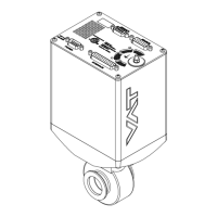
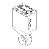
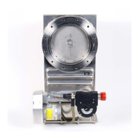
1. Install valve [1] into the vacuum system. Valve seat side must faced process chamber. The valve seat side is indicated
by the symbol " " on the valve flange.
Caution: Do not tighten the flange screws stronger than indicated under «Tightening torque».
Caution: Do not admit higher forces to the valve than indicated under «Admissible forces».
Note: Make sure that enough space is kept free to do preventive maintenance work. The required space is indicated
on the dimensional drawing.
Note: Control unit of valves with ISO-KF flanges (615 . . – K . . . ) needs support when mounted on horizontal piping
and control unit does not hang.
2. Install a ground connection cable at controller. Refer to «Electrical connection»
3. Install sensor(s) [2] according to the recommendations of the sensor manufacturer and directives given under
«Requirements to sensor connection».
4. Connect pressure sensor cable [3] to sensor(s) and then to valve (connector: SENSOR). Refer to chapter «Electrical
connection» for correct wiring.
Note: 61534-KEAQ-AQU2 supports 2 sensor(s).
5. Connect valve to remote control unit [4] (connector: INTERFACE). Refer to «DeviceNet connection» for correct wiring.
6. Connect power supply [5] to valve (connector: POWER). Refer to chapter «Electrical connection» for correct wiring.
Note: To provide power to the valve motor pins 4 and 8 must be bridged, otherwise motor interlock is active and the
valve enters the safety mode and is not operative. Refer also to «Safety mode».
7. This valve may optionally be equipped with a heating device. Connect VAT heating device according to manual of
respective heating device.
8. Perform «Setup procedure» to prepare valve for operation.
Note: Without performing the setup procedure the valve will not be able to do pressure control.
2.3 Tightening torque
2.3.1 Mounting of ISO-KF flanges
Tightening torques for ISO-KF flange connections depends on the type of seal which is used. Follow recommendations of
seal manufacturer.

 Loading...