Installation, Operating & Maintenance Instructions
Series 615 DN 40 (I.D. 1½”), DeviceNet
VAT Vakuumventile AG, CH-9469 Haag, Switzerland
Tel +41 81 771 61 61 Fax +41 81 771 48 30 CH@vatvalve.com www.vatvalve.com
3.5 Display information
3.5.1 Display controller
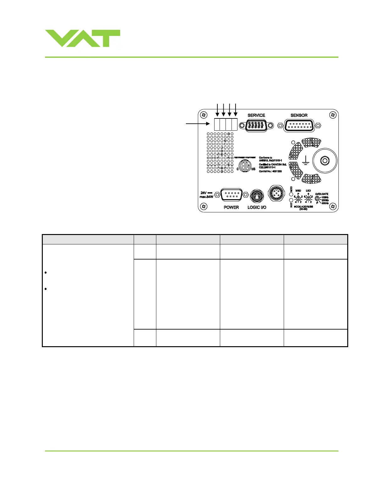
There is a 4 digit display located on the
panel. It displays configuration, status
and position information. For details see
following tables.
Power up:
At first all dots are illuminated then
configuration is displayed:
Firmware version [e.g. 1F00]
(1
st
information for about 2s)
Controller configuration
(2
nd
information for about 2s)
SYNC indicates that power up
synchronization is running.
In case D999 is displayed, motor
interlock is active. Refer to
«Safety mode» for details.
0
= basic
1
= with SPS
1)
2
= with PFO
2)
3
= with SPS
1)
and PFO
2)
1
= 1 sensor version
2
= 2 sensor version
1) SPS = optional ±15 VDC Sensor Power Supply module
2) PFO = Power Failure Option

 Loading...


