Installation, Operating & Maintenance Instructions
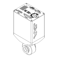
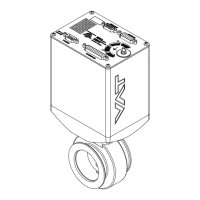
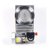
Series 615 DN 40 (I.D. 1½”), DeviceNet
VAT Vakuumventile AG, CH-9469 Haag, Switzerland
Tel +41 81 771 61 61 Fax +41 81 771 48 30 CH@vatvalve.com www.vatvalve.com
Contents:
1 Use of product ........................................................................................................................................................... 5
1.1 Technical data .................................................................................................................................................. 6
2 Installation ................................................................................................................................................................. 7
2.1 Unpacking ........................................................................................................................................................ 8
2.2 Installation into the system ............................................................................................................................... 8
2.3 Tightening torque ............................................................................................................................................. 9
2.3.1 Mounting of ISO-KF flanges ................................................................................................................ 9
2.4 Admissible forces ........................................................................................................................................... 10
2.4.1 Admissible forces at controller ........................................................................................................... 11
2.5 Requirements to sensor connection ............................................................................................................... 12
2.6 Electrical connection ...................................................................................................................................... 13
2.6.1 Ground connection ............................................................................................................................ 13
2.6.2 Sensor supply concepts ..................................................................................................................... 14
2.6.3 Power and sensor connection ( 15 VDC sensors) with optional SPS module ................................... 15
2.6.4 DeviceNet connection ..................................................................................................................... 16
2.6.5 LOGIC I/O .......................................................................................................................................... 17
2.6.6 Digital input ........................................................................................................................................ 18
2.6.7 Digital output ...................................................................................................................................... 18
2.6.8 Service port connection ..................................................................................................................... 18
3 Operation ................................................................................................................................................................ 19
3.1 Introduction .................................................................................................................................................... 19
3.1.1 Local operation .................................................................................................................................. 20
3.1.2 Remote operation .............................................................................................................................. 20
3.1.3 Safety mode....................................................................................................................................... 21
3.1.4 Service indication ............................................................................................................................... 21
3.2 Operation under increased temperature ........................................................................................................ 21
3.3 Behavior during power up .............................................................................................................................. 21
3.4 Behavior in case of power failure ................................................................................................................... 22
3.5 Display information ......................................................................................................................................... 23
3.5.1 Display controller ............................................................................................................................... 23
3.6 Setup procedure ............................................................................................................................................. 24
3.6.1 DeviceNet
®
configuration ................................................................................................................... 25
3.6.2 DeviceNet® LEDs .............................................................................................................................. 27
3.6.3 LOGIC I/O configuration .................................................................................................................... 29
3.6.4 Valve configuration ............................................................................................................................ 30
3.6.5 Sensor configuration .......................................................................................................................... 30
3.6.6 ZERO ................................................................................................................................................. 31
3.6.7 Pressure control configuration ........................................................................................................... 32
3.7 Close valve .................................................................................................................................................... 38
3.8 Open valve ..................................................................................................................................................... 38
3.9 Position control............................................................................................................................................... 39
3.10 Pressure control ............................................................................................................................................. 39
3.10.1 Pressure control operation with 2 sensors ......................................................................................... 40
3.11 Tuning of pressure control performance ........................................................................................................ 40
3.11.1 Tuning of pressure control with adaptive algorithm ............................................................................ 41
3.11.2 Tuning of pressure control performance with Fixed algorithm ........................................................... 46
3.11.3 Tuning of control performance with soft pump algorithm ................................................................... 50
4 DeviceNet interface ............................................................................................................................................... 53
4.1 Introduction .................................................................................................................................................... 53
4.2 Factory default assemblies............................................................................................................................. 54
4.3 Messaging Format ......................................................................................................................................... 54
4.3.1 Explicit Messaging Connections ........................................................................................................ 54
4.3.2 I/O Poll Messaging Connections ........................................................................................................ 55
4.4 Object ............................................................................................................................................................. 56
4.4.1 Object Model for the Process Control Valve Device .......................................................................... 56

 Loading...