Installation, Operating & Maintenance Instructions
Series 615 DN 40 (I.D. 1½”), DeviceNet
VAT Vakuumventile AG, CH-9469 Haag, Switzerland
Tel +41 81 771 61 61 Fax +41 81 771 48 30 CH@vatvalve.com www.vatvalve.com
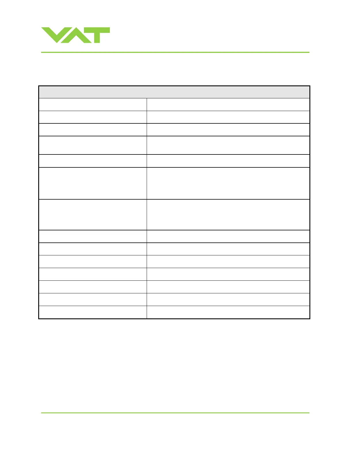
1.1 Technical data
Control and actuating unit
+24 VDC (±10%) @ 0.5 V pk-pk max.
3 W max. (from DeviceNet®)
Sensor power supply output 2)
±15 VDC (±5%) / 1000 mA max.
Sensor input
Signal input voltage / Input resistance
ADC resolution
Sampling time
0-10 VDC / Ri>100 kΩ (linear to pressure)
0.23 mV
10 ms
PFO
3)
battery pack
Charging time
Durability
2 minutes max.
up to 10 years @ 25°C ambient
refer to «Durability of power fail battery» for details
+0 °C to +50 °C max. (<35 °C recommended)
Pressure control accuracy
5 mV or 0.1% of setpoint, whichever is greater
Position resolution / position control capability
Closing time throttling only
Opening time throttling only
Closing time throttling & isolation
Opening time throttling & isolation
1) Internal overcurrent protection by a PTC device.
2) Refer to chapter «Sensor supply concepts» for details.
3) PFO = Power Failure Option. Refer to «Behavior in case of power failure» for details.

 Loading...


