Installation, Operating & Maintenance Instructions
Series 615 DN 40 (I.D. 1½”), DeviceNet
VAT Vakuumventile AG, CH-9469 Haag, Switzerland
Tel +41 81 771 61 61 Fax +41 81 771 48 30 CH@vatvalve.com www.vatvalve.com
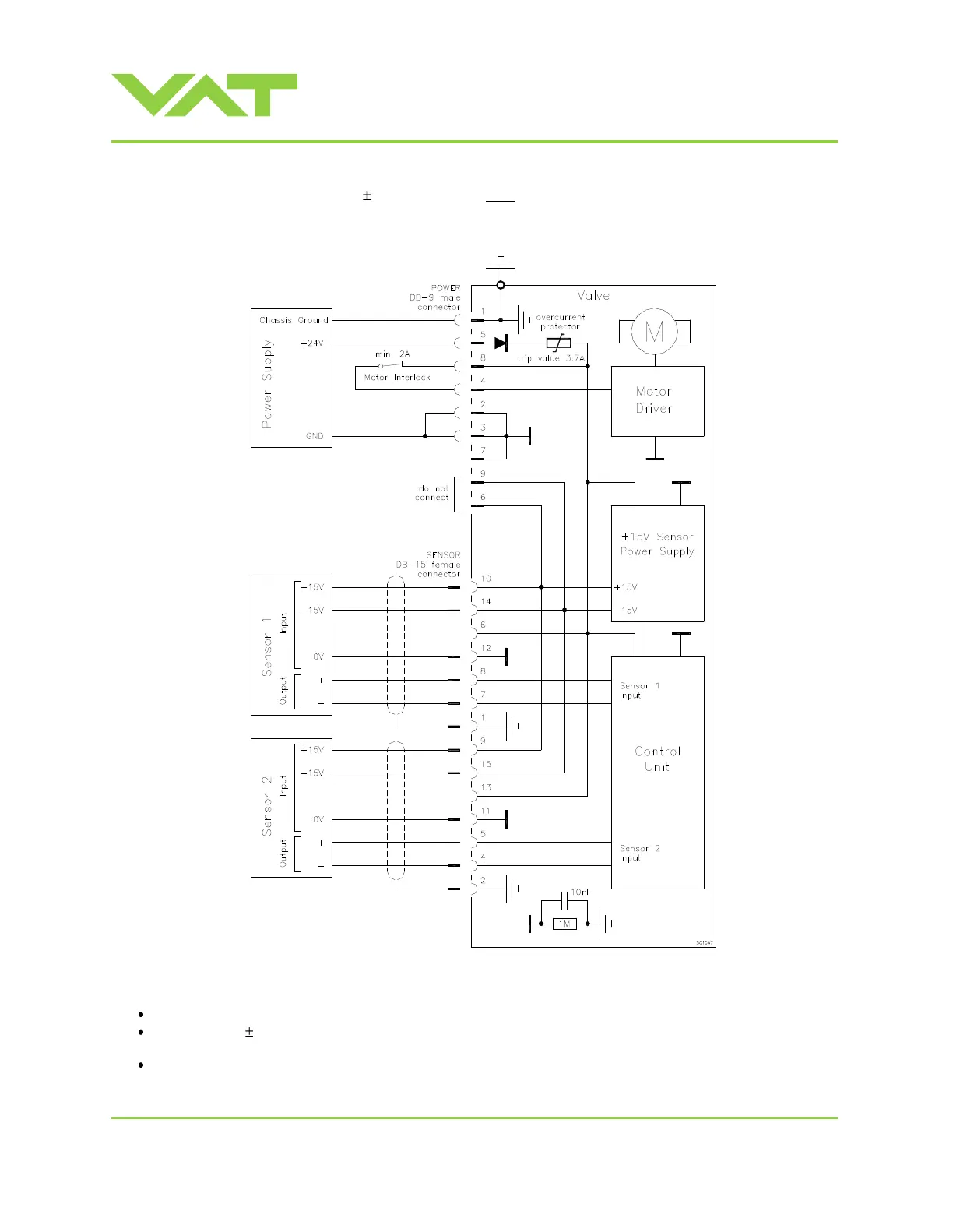
2.6.3 Power and sensor connection ( 15 VDC sensors) with optional SPS module
[615 . . - . . A . - . . . . / 615 . . - . . C . - . . . . versions only]
Note:
Use shielded sensor cable(s). Keep cable as short as possible, but locate it away from noise sources.
Connect the 15 VDC sensors at DB–15 female sensor connector exactly as shown in the drawing above. Do not
connect other pins that may damage sensors, power supply or controller!
Connector: Use only screws with 4-40UNC thread for fastening the connectors!
Pins 4 and 8 must be bridged for operation!
An optional switch would allow for motor
interlock to prevent valve from moving.
Low range sensor may be connected to
sensor 1 or sensor 2 input.
Do configuration accordingly.

 Loading...


