EasyManua.ls Logo

VAT 65046 Series - User Manual

Default Icon
51 pages
Print Icon
To Next Page IconTo Next Page
Loading...
Installation, Operating & Maintenance Instructions
Series 650, DN 100 – 250 (I.D. 4" - 10")
VAT Vakuumventile AG, CH-9469 Haag, Switzerland
Tel ++41 81 771 61 61 Fax ++41 81 771 48 30 Email reception@vat.ch www.vatvalve.com
258550EE
2007-05-11
1/51
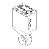
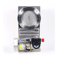
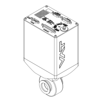
Pendulum control & isolation valve
with Logic interface
This manual is valid for the valve ordering number(s):
650 . . - . . GC - . . . . (1 sensor input)
650 . . - . . GE - . . . .
(2 sensor inputs)
650 . . - . . AC - . . . .
(1 sensor input / ±15V SPS)
650 . . - . . AE - . . . .
(2 sensor inputs / ±15V SPS)
650 . . - . . HC - . . . .
(1 sensor input / PFO)
650 . . - . . HE - . . . .
(2 sensor inputs / PFO)
650 . . - . . CC - . . . .
(1 sensor input / ±15V SPS / PFO)
650 . . - . . CE - . . . .
(2 sensor inputs / ±15V SPS / PFO)
SPS = Sensor Power Supply PFO = Power Failure Option
configured with firmware 650P.1D.00
The fabrication number is indicated on each product as per the label
below (or similar):
made in Switzerland
Fabrication No.: patented
. .
650
. .
. . . .
. . . . / . . . .
A
Fabrication number
Explanation of symbols:
Read declaration carefully before you start any other
action!
Keep body parts and objects away from the valve
opening!
Attention!
Hot surfaces; do not touch!
Product is in conformity with EC guidelines!
Loaded springs and/or air cushions are potential
hazards!
Disconnect electrical power and compressed air
lines. Do not touch parts under voltage!
Wear gloves!
Read these «Installation, Operating & Maintenance Instructions» and the enclosed «General
Safety Instructions» carefully before you start any other action!

Questions and Answers

  • H
    hsimsAug 17, 2025
    How to fix VAT 65046 when remote operation does not work?
    • K
      kaylee58Aug 18, 2025
      If remote operation of the VAT Control Unit is not working, it might be because local operation via the service port is active, or the safety mode is engaged (indicated by a 'D' on the display). Ensure you switch to remote operation and that the motor has sufficient power for operation.
  • K
    Kiara MahoneyAug 19, 2025
    Why is VAT 65046 Control Unit PRESSURE CONTROL not optimal?
    • C
      Craig LongAug 20, 2025
      If the PRESSURE CONTROL of your VAT Control Unit isn't working optimally, ensure that the setup procedure has been completed, and perform LEARN. Also, make sure ZERO was performed before LEARN. If LEARN was interrupted, repeat it with a stable gas flow. Tune the valve for your specific application, and verify that the sensor range is suitable, ensuring the controlled pressure is within 3% and 98% of the sensor's full scale. Use a shielded sensor cable to reduce noise.
  • T
    travis72Aug 22, 2025
    What to do if pressure is not ‘0’ after ZERO PRESSURE CONTROL on VAT 65046?
    • J
      John RoyAug 22, 2025
      If the pressure isn't at ‘0’ after performing ZERO PRESSURE CONTROL on your VAT Control Unit, it could be due to several reasons. The sensor voltage might be shifting, or the system might not be pumped to base pressure. It's also possible that the sensor offset voltage exceeds ±1.4V, the safety mode is active (check for 'D' on the display), PRESSURE CONTROL isn't selected (check for 'P' on the display), or LEARN hasn't been done. Wait until the sensor stabilizes before performing ZERO. Ensure the valve is open and the chamber is at base pressure, and provide power to the motor. If necessary, replace the pressure gauge. Select PRESSURE CONTROL mode and perform LEARN.
  • C
    Casey GarciaAug 25, 2025
    Why OPEN VALVE does not work on VAT Control Unit?
    • P
      Patrick HuffmanAug 26, 2025
      If the OPEN VALVE function isn't working on your VAT Control Unit, it might be because the safety mode is active, indicated by a 'D' on the display. To resolve this, ensure that the motor has sufficient power for operation.
  • J
    Joshua FordAug 27, 2025
    Why CLOSE VALVE does not work on VAT 65046?
    • T
      Timothy ShawAug 27, 2025
      If the CLOSE VALVE function isn't working on your VAT Control Unit, it might be because the safety mode is active, indicated by a 'D' on the display. To resolve this, ensure that the motor has sufficient power for operation.
  • D
    douglaskimAug 30, 2025
    What to do if POSITION CONTROL does not work on VAT 65046 Control Unit?
    • E
      Elizabeth MortonAug 30, 2025
      If the POSITION CONTROL on your VAT Control Unit isn't working, it could be due to the safety mode being active (check for 'D' on the display). It may also be that POSITION CONTROL is not selected (check for 'V' on the display). Provide power to the motor to allow for operation. Select POSITION CONTROL mode.
  • J
    James MullinsSep 1, 2025
    Why ZERO does not work on VAT 65046 Control Unit?
    • T
      Timothy BrowningSep 1, 2025
      If the ZERO function isn't working on your VAT Control Unit, ensure the valve is in the open position (check for 'O' on the display) and that ZERO is enabled. Open the valve and bring the chamber to base pressure before performing ZERO.
  • L
    Laura JohnsonSep 4, 2025
    What does «SR» mean on VAT Control Unit display?
    • A
      Anna DavisSep 4, 2025
      If the display of your VAT Control Unit shows «SR» (Service Request), it indicates that the valve unit is heavily contaminated or the gate seal is heavily sticking. Clean the valve and/or replace the gate seal.
  • R
    richard05Sep 6, 2025
    What does error «E 22» mean on VAT 65046?
    • M
      Michaela TaylorSep 6, 2025
      If the display of your VAT Control Unit shows «E 22» (fatal error - rotation angle of valve plate limited during operation), it means the valve plate is mechanically obstructed. Resolve the obstruction.
  • J
    Jeffrey BauerSep 9, 2025
    What does error «E 40» mean on VAT 65046 Control Unit?
    • H
      Heidi BuckSep 9, 2025
      If the display on your VAT Control Unit shows «E 40» (fatal error - motor driver failure detected), replace the control unit.

Summary

Pendulum Control & Isolation Valve

Technical Data

Installation

Installation into the System

Guidelines for correctly installing the valve into the vacuum system.

Mounting and Forces

Sensor Connection Requirements

Electrical Connection

Operation Modes

Operational Behavior

Setup and Calibration

Setup Procedure

Step-by-step guide to configure the valve for operation.

Valve and Sensor Configuration

Setting valve plate position and sensor configuration.

ZERO Calibration

Compensating sensor offset voltage for accurate zero point.

LEARN Calibration

Adapting the PID controller to the vacuum system characteristics.

Control Modes

Position Control

Directly controlling the valve's pendulum plate position.

Pressure Control

Tuning of Control Performance

Procedures to optimize pressure control performance.

Gain Factor Adjustment

Sensor Delay Adjustment

Setpoint Ramp Adjustment

Valve Speed Adjustment

Troubleshooting

Maintenance and Repairs

Maintenance Procedures

Recommended procedures for routine maintenance and seal replacement.

VAT 65046 Series Specifications

General IconGeneral
TypeControl Unit
ModelVAT 65046 Series
Supply Voltage24 V DC
Input Voltage24 V DC
Output Voltage24 V DC
ProtectionIP20
Communication InterfaceRS-485
Operating Temperature0°C to +50°C

Related product manuals