M
Matthew SanchezAug 31, 2025
What does «D 0» mean on VAT Control Unit display?
- MMatthew GonzalesAug 31, 2025
«D 0» on the display means the Motor Interlock is open. This is caused by motor power not being supplied. Provide power to the motor.

What does «D 0» mean on VAT Control Unit display?
«D 0» on the display means the Motor Interlock is open. This is caused by motor power not being supplied. Provide power to the motor.
What does it mean when my VAT 615 display shows «E 40» (fatal error - motor driver failure detected)?
If your VAT Control Unit displays «E 40», it indicates a fatal error: a motor driver failure has been detected. Replace the control and actuating unit.
What does error «E 21» on VAT Control Unit mean?
Error «E 21» indicates that the rotation angle of the valve plate is limited during power up. This could be due to a valve plate centric adjustment issue, a heavily contaminated valve unit, or a mechanically obstructed valve plate. Adjust the valve plate, clean the valve unit, resolve any obstruction, and reset the control unit.
What to do if VAT Control Unit display shows «E 40»and position is 009999?
To resolve a 'Display shows «E 40»and position is 009999' error on your VAT Control Unit, replace the control and actuating unit according to the «Maintenance procedure».
What should I do if my VAT Control Unit's CLOSE VALVE does not work?
If the CLOSE VALVE function is not working on your VAT Control Unit, check if the safety mode is active (indicated by a 'D' on the display). Provide power to the motor to allow for operation.
Why does remote operation not work on my VAT Control Unit?
To address remote operation issues with the VAT Control Unit, ensure you switch to remote operation mode. Also, verify that the motor is receiving power. Refer to the «Electrical connection» section for detailed instructions.
Why is the PRESSURE CONTROL not optimal on my VAT Control Unit?
To address suboptimal PRESSURE CONTROL on your VAT Control Unit: 1. Completely perform the «Setup procedure». 2. Perform LEARN, referring to «LEARN» for details. 3. Perform ZERO, then repeat LEARN, consulting «Setup procedure» for details. 4. Repeat LEARN, referring to «LEARN» for details, ensuring stable gas flow. 5. Tune the valve for your application, referring to «Tuning of control performance» for details. 6. Use a sensor with a suitable range (controlled pressure should be >3% and < 98% of the sensor's full scale). 7. Ensure a shielded sensor cable is used.
What to do if VAT 615 OPEN VALVE does not work?
If OPEN VALVE does not work, it might be because safety mode is active or maintenance mode is active. Provide power to the motor.
Why VAT Control Unit remote operation does not work?
If remote operation doesn't work, it could be because local operation via the service port is active or safety mode is active. Try switching to remote operation and provide power to the motor.
What to do if VAT Control Unit PRESSURE CONTROL does not work?
If the PRESSURE CONTROL does not work, it might be because the safety mode is active, PRESSURE CONTROL is not selected, or LEARN hasn't been done. Provide power to the motor, select PRESSURE CONTROL mode, and perform LEARN.
| Brand | VAT |
|---|---|
| Model | 615 Series |
| Category | Control Unit |
| Language | English |
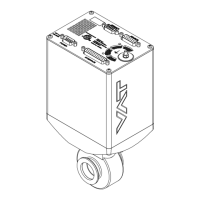
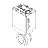
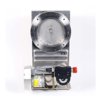
Detailed specifications for the control and actuating unit and valve unit, including electrical and mechanical parameters.
Guidelines for installing the valve into the vacuum system, emphasizing safety precautions.
Guidelines for sensor connection to ensure fast pressure response time.
Details on electrical connections, including ground strap and connector types.
Wiring diagram for power and sensor connections with the optional SPS module.
Details DeviceNet connector type, pinout, wire colors, and signal descriptions.
Step-by-step guide to configure the valve for operation.
How to configure node number, baudrate and DeviceNet parameters.
Options for configuring pressure control algorithms: Adaptive, Fixed, and Soft Pump.
Procedure for learning system characteristics for adaptive pressure control.
How to configure Fixed PI parameters for pressure control.
How to configure the soft pump algorithm for pressure ramps.
Overview of tuning procedures for optimizing pressure control performance.
Step-by-step tuning procedures for the adaptive algorithm.
How to adjust the gain factor to optimize stability and response time.
How to adjust sensor delay to improve stability.
How to adjust setpoint ramp time for better pressure response.
How to adjust valve plate actuating speed for optimal response.
Procedures for tuning the fixed algorithm parameters (P-Gain, I-Gain).
How to tune the soft pump algorithm for pressure ramps.
Step-by-step guide for replacing the plate o-ring.
Procedure for replacing shaft feedtrough seals and plate o-ring.
Procedure for retrofitting or replacing control and actuating unit boards.