Installation, Operating & Maintenance Instructions
Series 650, DN 100 – 250 (I.D. 4" - 10")
VAT Vakuumventile AG, CH-9469 Haag, Switzerland
Tel ++41 81 771 61 61 Fax ++41 81 771 48 30 Email reception@vat.ch www.vatvalve.com
258550EE
2007-05-11
18/51
3.2 Operation under increased temperature
This valve may be operated in the temperature range mentioned in chapter «1.1 Technical data».
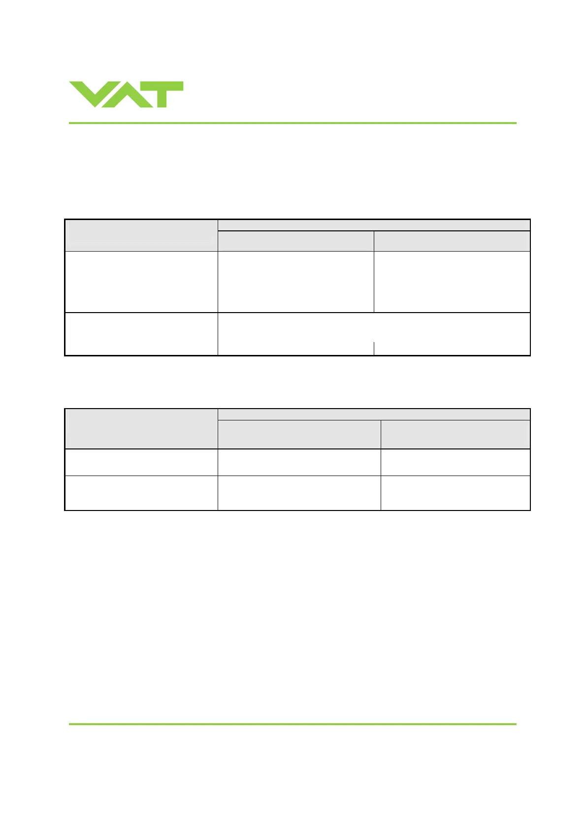
3.3 Behavior during power up
Reaction of valve:
Valve position before
power up:
Valve power up configuration = closed
(defaullt)
Valve power up configuration = open
Closed (isolated) Valve remains closed.
Display shows alternately ‘C C’ and
‘INIT’.
Syncronization will be done when first
movement command is received.
Valve runs to max. throttle position to
detect the limit stops to synchronize.
Display shows configuration of product
resp. ‘SYNC’ until synchronization is
done.
Valve position after power up is open.
Valve runs to max. throttle position to detect limit stop for synchronization.
Display shows configuration of product resp. ‘SYNC’ until synchronization is
done.
All other than closed (not isolated)
Valve position after power up is closed
Valve position after power up is open
Refer also to chapter «3.5 Display information».
3.4 Behavior in case of power failure
Reaction of valve:
Valve position before
power failure:
Without Power Failure Option (PFO)
650 . . - . . G . - . . . .
650 . . - . . A . - . . . .
With Power Failure Option (PFO)
650 . . - . . H . - . . . .
650 . . - . . C . - . . . .
Closed (isolated) Valve remains closed.
Valve remains closed.
Display indicates F
Valve open or in any intermediate
position
Sealing ring moves down and blocks the
pendulum plate at the current position.
Valve will close or open depending
on valve configuration *).
Display indicates F
*) Provided that battery pack of the VAT controller is charged. Charging time after power up is 2 minutes .
All parameters are stored in a power fail save memory.
 Loading...


