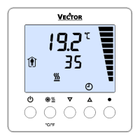
TCY3-T0121R Engineering Manual
Doc: 70-000002 V1.0, 20101115 © Vector Controls GmbH, Switzerland Page 18
Subject to alteration
Control parameters Temperature Input (Loop 1)
Parameter Description Range Default
1L 00 Standby set point shift 0…100° 5.0°C (10°F)
1L 01 Minimum set point limit for heating -40…215°C 10°C (50°F)
1L 02 Maximum set point limit for heating -40…215°C 28°C (82°F)
1L 03 Minimum set point limit for cooling -40…215°C 18°C (64°F)
1L 04 Maximum set point limit for cooling -40…215°C 34°C (92°F)
1L 05 Dead zone between heating & cooling set point X
DZ
0…100° 1.0° (2°F)
1L 06 Cascade Control:
Set point of this loop provided by a PID sequence of loop 2.
0 = No cascade control
1 = Setpoint provided by reverse sequence of LP2
2 = Setpoint provided by direct sequence of LP2
3 = Setpoint provided by reverse and direct sequence of LP2
0…3 0
1L 07 Summer – Winter compensation
0 = Disabled
1 = Winter Compensation only
2 = Summer compensation only
3 = Winter and summer compensation
0…3 0
1L 08 Automatic change of Heat / Cool setting by demand
OFF = Manual (2-pipe)
ON = Automatic (4-pipe)
ON, OFF OFF
PID Control Sequence
Parameter Description Range Default
1L 09 P – band heating X
PH
0…100° 2.0°C (4.0°F)
1L 10 P – band cooling X
PC
0…100° 2.0° (4.0°F)
1L 11 K
IH
, Integral gain heating, in 0.1 steps,
0 disables ID part
low value = slow reaction
high value = fast reaction
0…25.5 0.0
1L 12 K
IC
, Integral gain cooling, in 0.1 steps, 0 disables I part 0…25.5 0.0
1L 13 T
I
interval time speed: OFF = Seconds, ON = Minutes ON, OFF OFF (sec)
1L 14 T
I
, measuring interval integral
low value = fast reaction
high value = slow reaction
0…255 1 sec
Digital Control Sequence
Parameter Description Range Default
1L 15 Action of stages
0 = Cumulative: 1. Q
H1
, 2. Q
H1
+Q
H2
1 = Single: 1. Q
H1
, 2. Q
H2
2 = Digital: 1. Q
H1
, 2. Q
H2
, 3. Q
H1
+ Q
H2
0…2 0
1L 16 Offset heating stage 1: Q
H1
0…100° 0.0° (0.0°F)
1L 17 Offset heating stage 2: Q
H2
0…100° 2.0° (4.0°F)
1L 18 Offset heating stage 3: Q
H3
0…100° 4.0° (8.0°F)
1L 19 Offset cooling stage 1: Q
C1
0…100° 0.0° (0.0°F)
1L 20 Offset cooling stage 2: Q
C2
0…100° 2.0° (4.0°F)
1L 21 Offset cooling stage 3: Q
C3
0…100° 4.0° (8.0°F)
1L 22 Switching Hysteresis X
H
0…100° 0.5° (1.0°F)
1L 23 Delay Switching on / off 0…255s 10s
1L 24 Delay Heat / Cool change over 0…255 Min 5 Min
 Loading...
