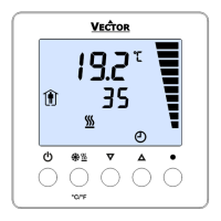
TCY3-T0121R Engineering Manual
Doc: 70-000002 V1.0, 20101115 © Vector Controls GmbH, Switzerland Page 20
Subject to alteration
Temperature Input configuration
Parameter Description Range Default
IP 00 TI1: Control input of loop 1:
OFF = Internal sensor
ON = External sensor
ON, OFF OFF
IP 01 TI1: Samples taken for averaging control signal
1…255 10
IP 02 TI1: Calibration
-10…10 0
IP 03 Alarm 1: Alarm for lower limit of temperature input of LP1
OFF = Not active
ON = Active
OFF, ON OFF
IP 04 Alarm 1 low limit of temperature input
-40…215 °C 5°C (40°F)
IP 05 Alarm 1 Hysteresis for alarm setback
0…100 ° 5°C (10°F)
IP 06 Alarm 2: Alarm for upper limit of temperature input of LP1
OFF = Not active
ON = Active
OFF, ON OFF
IP 07 Alarm 2 high limit of temperature input
-40…215 °C 50°C (122°F)
IP 08 Alarm 2 Hysteresis for alarm setback
0…100 ° 5°C (10°F)
Analog Input configuration
Parameter Description Range Default
IP 09 AI1: Calibration -10…10 0
IP 10 AI1: Minimum limitation of input signal 0 – Max % 0 %
IP 11 AI1: Maximum limitation of input signal Min – 100% 100%
IP 12 AI1: Lower universal sensor measuring range limit -50…Max 0
IP 13 AI1: Upper universal sensor measuring range limit Min…205 100
IP 14 AI1: Samples taken for averaging control signal 1…255 3
IP 15 AI1: Unit & range of analog input:
0 = no unit
1 = %
2 = °C / °F
3 = x10
4 = x100
0 – 4 1
Alarms 3 and 4 follow control input of Loop 2
Parameter Description Range Default
IP 16 Alarm 3: Alarm for lower limit of universal input of LP2
OFF = Not active
ON = Active
OFF, ON OFF
IP 17 Alarm 3 low limit of universal input Acc input 0%
IP 18 Alarm 3 Hysteresis Acc input 5%
IP 19 Alarm 4: Alarm for upper limit of universal input of LP2
OFF = Not active
ON = Active
OFF, ON OFF
IP 20 Alarm 4 high limit of universal input Acc input 100%
IP 21 Alarm 4 Hysteresis Acc input 5%
Summer – Winter Compensation
Parameter Description Range Default
IP 22 Selection of Compensation Input
OFF = Thermistor Input TI
ON = Analog Input AI
ON, OFF OFF
IP 23 Winter Compensation:
OFF = setpoint is shifted negative to lower setpoint limit
ON = setpoint is shifted positive to upper setpoint limit
ON, OFF OFF
IP 24 Winter Compensation (Setpoint shift with low compensation signal)
Lower Limit: input signal with maximum setpoint shift
-40…215 °C -30°C (-22°F)
IP 25 Winter Compensation (Setpoint shift with low compensation signal)
Upper Limit: Input signal at begin of setpoint shift.
-40…215 °C 0°C (32°F)
IP 26 Summer Compensation:
OFF = setpoint is shifted negative to lower setpoint limit
ON = setpoint is shifted positive to upper setpoint limit
ON, OFF ON
IP 27 Summer Compensation (Setpoint shift with high compensation signal)
Lower Limit: input signal at begin of setpoint shift
-40…215 °C 30°C (86°F)
IP 28 Summer Compensation (Setpoint shift with high compensation signal)
Upper Limit: Input signal with maximum setpoint shift.
-40…215 °C 40°C (104°F)
IP 29 Hot / Cool Symbol while compensation is active
OFF= Hide symbol
ON= Show symbol
ON, OFF OFF
 Loading...
