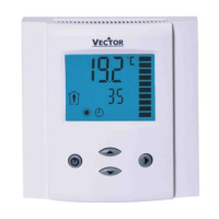
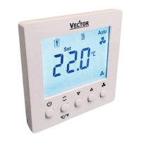
TCY3-T0121R Engineering Manual
Doc: 70-000002 V1.0, 20101115 © Vector Controls GmbH, Switzerland Page 21
Subject to alteration
Humidity Sensor Configuration (-H Version)
Parameter Description Range Default
IP 30 Humidity Sensor is Control Input of Loop 2 ON, OFF OFF
IP 31 Humidity Sensor Calibration -10…10 0
IP 32 Samples taken for averaging control signal 1…255 10
Remote Control
Parameter Description Range Default
IP 33 Configuration of remote control input (TI EXT)
0 = no remote control
1 = Occupation sensor – Comfort / Standby
2 = Occupation sensor – Comfort / Off
3 = Heat / Cool change by open contact. Contact open = Heat
4 = Heat / Cool change by open contact. Contact open = Cool
5 = Auto change over depending on supply temperature
0…5 0
IP 34 Activation delay (Minutes) = the time the binary input needs to be open
before standby/off mode is activated.
0…255 min 5
IP 35 Auto Change Over limit cooling -40…215 °C 16°C (60°F)
IP 36 Auto Change Over limit heating -40…215 °C 28°C (82°F)
Analog Output
Parameter Description Range Default
OP 00 AO1: Selection of control loop or special function
0 = OFF
1 = Loop 1
2 = Loop 2
3 = Dehumidify in 4 pipe systems
(Max LP1 cooling and LP2 direct acting)
4 = Manual override (0 – 100%)
5 = Feedback of temperature input or set point
6 = Feedback of floating output
0 – 6 1
OP 01 AO1: Configuration of output signal depending on OP00
If OP00 = 1,2 (control loop 1 or 2) select sequence:
0 = Heating, Reverse Y
H1
, Y
R1
1 = Cooling, Direct Y
C1
, Y
D1
2 = Heating and Cooling (2 pipe system), Y
H1
+ Y
C1
, Y
R1
+ Y
D1
3 = VAV function
If OP00 = 4 (manual override) Choose Manual override steps:
0 = 0…100%
1 = 0…10
2 = ON/OFF
If OP00 = 5 (Feedback), select feedback source:
0 = Temperature input loop 1 (acc IP00)
1 = Set point loop 1
2 = Set point loop 2
3 = Humidity sensor (-H Version)
4 = Analog input
0 – 4 0
OP 02 AO1: Minimum limitation of output signal 0 – Max % 0
OP 03 AO1: Maximum limitation of output signal Min – 100% 100%
OP 04 AO1: Maximum limitation in standby mode 0 – 100 % 50%
OP 05 AO1: VAV function maximum limitation in heating mode 0…100% 50%
OP 06 AO1: Binary function – Convert AO with use of accessory to three binary
outputs with following switching steps: 0, 30, 70, 100%
ON, OFF OFF
OP 07 AO1: Choose alarm
0 = no action
1 = TI1 ALA1: low temperature limit
2 = TI1 ALA2: high temperature limit
3 = TI1 ALA1 and ALA2: low or high temperature alarm active
4 = AI1 ALA3: low signal limit
5 = AI1 ALA4: high signal limit
6 = AI1 ALA3 and ALA4 low or high signal alarm active
7 = Any alarm active (ALA1 – ALA4)
0 - 7 0
OP 08 AO1: Action in case of alarm
OFF = close (Output is off 0%)
ON = open output (Output is on 100%)
ON, OFF OFF
OP 09 Temperature feedback minimum temperature -40…215 °C 0°C (32°F)
OP 10 Temperature feedback maximum temperature -40…215 °C 50° (122°F)
 Loading...
