TCY3-T0121R Technical Data
Doc: 70-000002 V1.0, 20101115 © Vector Controls GmbH, Switzerland Page 4
Subject to alteration
Selection of actuators and sensors
Temperature Sensors:
Use only our approved NTC sensors to achieve maximum accuracy. Recommended is SDB-Tn10-20 as Duct sensor, SRA-
Tn10 as Room sensor and SDB-Tn10-20 with AMI-S10 as immersion sensor.
Modulating Actuators:
Choose actuators with an input signal type of 0-10 V DC or 4-20 mA. Minimum and maximum signal limitations may be
set in software.
Floating Actuators:
Actuators with constant running time are recommended. Observe power limits on binary devices.
Binary auxiliary devices:
E.g. pumps, fans, on/off valves, humidifiers, etc. Do not directly connect devices that exceed 48 VAC, 2(1.2) A. Observe
startup current on inductive loads.
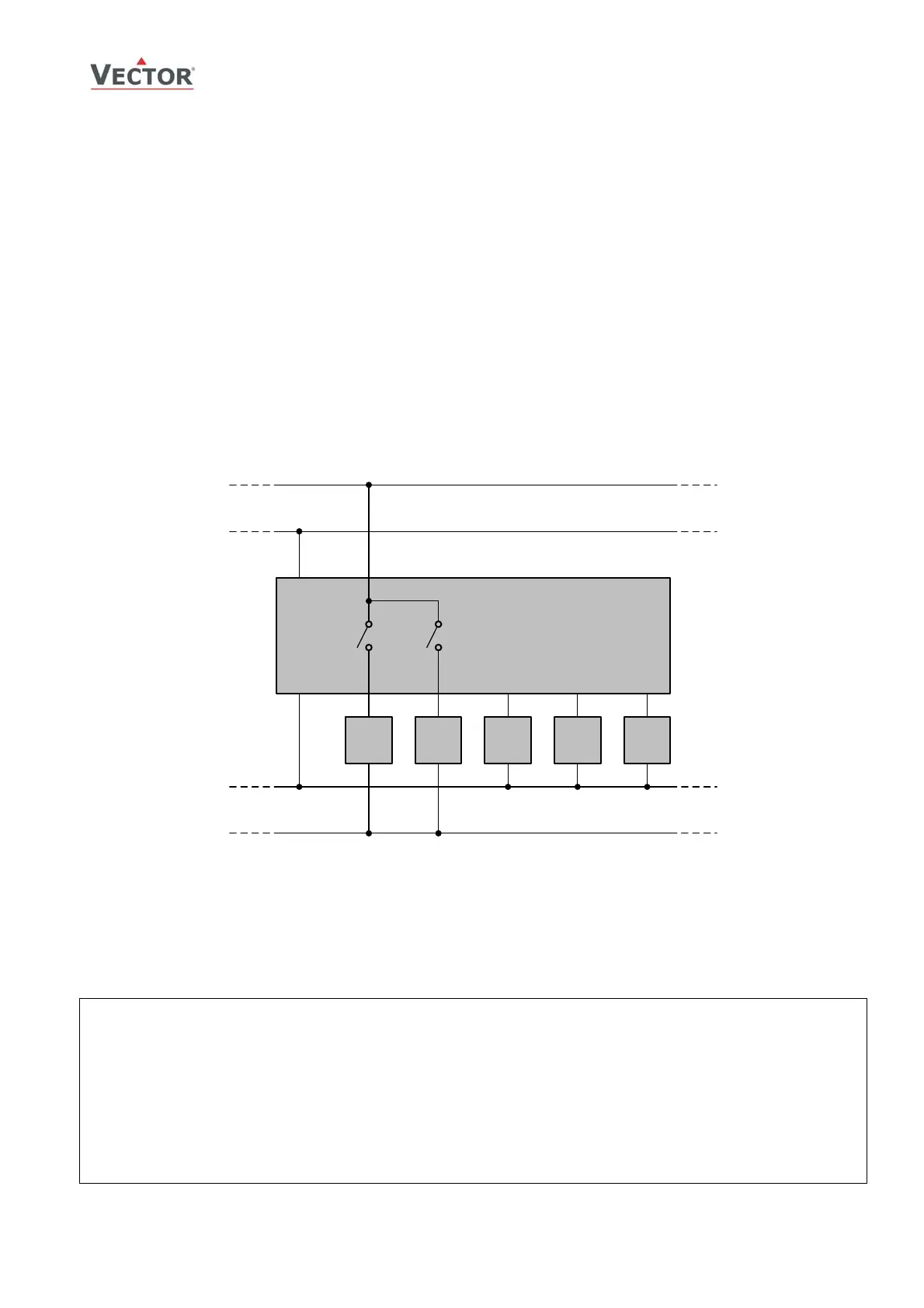
Connection diagram
Y
B1
Y
B2
Y
M1
X
A1
R
T
23
145678
TCY3-T0121..
24V AC/DC ±10%
0...48 V
AC
0...30 V
DC
0V (GND)
0V
Description:
Y
B1
Binary output 1: 0…48 VAC or 0…30 VDC
Y
B2
Binary output 2: 0…48 VAC or 0…30 VDC
X
A1
Analog input 1: 0…5 V, 0…10 V or
*
0…20 mA
Y
M1
Analog output 1: 0…10 V or
*
0…20 mA
R
T
Temperature input 1: NTC 10kΩ @ 25°C (77°F)
*
) selectable by jumper
U
WARNING:
Power supply is half-wave rectified:
Signal ground = Power ground
Connect through a safety isolation transformer
!