TCY3-T0121R Installation
Doc: 70-000002 V1.0, 20101115 © Vector Controls GmbH, Switzerland Page 5
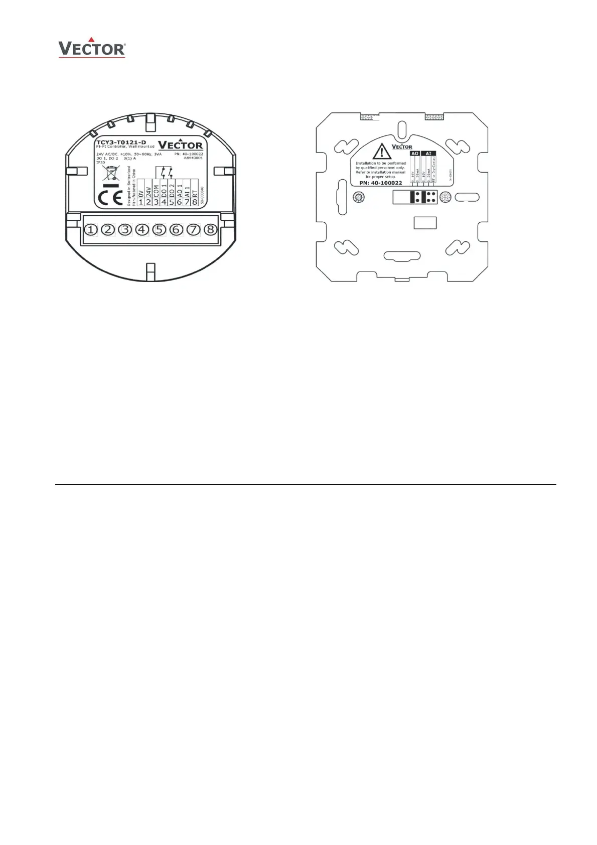
Connection terminals and jumpers
Terminal-description:
1. Connection for power-supply (24 V AC/DC, ±10%).
In case of DC, connect the negative power-
terminal. Common connection for analog in- and
outputs.
2. Connection for power-supply (24 V AC/DC, ±10%).
In case of DC, connect the positive power-terminal
3. Common for relays
4. Switched contact “DO 1” (Max. 2 (1.2A)
5. Switched contact “DO 2” (Max. 2 (1.2A)
6. Analog-output “AO 1” (Jumper-selectable between
0…10 V or 0…20 mA)
7. Analog input “AI 1” (Jumper-selectable between
0…10 V or 0…20 mA)
8. Thermistor input “RT” (Thermistor Sxx-Tn10)
Jumper-settings
(standard version shown):
Jumpers are mounted vertically only.
1. AO - Selection of output type:
a. Left position: voltage output (0…10 V),
factory default
b. Right position: current output (0…20 mA)
2. AI - Selection of input type:
a. Left position: voltage input (0…10 V),
factory default
b. Middle position: current input (0…20 mA)
c. Right position: RT or dry-contact input
Mechanical Design and installation
The unit consists of two parts: (a) The power case with attached mounting plate and (b) the front part.
Mounting location
• On an easy accessible interior wall, approx. 1.5 m (4.5’) above the floor in an area of average temperature.
• Avoid exposure to direct sunlight or other heat sources, e.g. the area above radiators and heat emitting electrical
equipment.
• Avoid locations behind doors, outside walls and below or above air discharge grills and diffusers.
• Location of mounting is less critical if external temperature sensors are used
Installation
1. Connect the wires to be connected to the terminals of the power case according to wiring diagram
2. Install the mounting plate to the flush mounting box. Make sure that the nipple with the front holding screw is
facing to the ground. Make sure the mounting screw heads do not stand out more than 5 mm (0.2”) off the
surface of the mounting plate.
3. Ensure that the jumpers are set correctly.
4. Slide the two latches located on the top of the front part into the hooks at the upper side of the mounting plate.
5. Carefully lower the front part until the interconnector reaches the mounting-plate. Continue pressing in a gentle
way until the front part is fully connected. While inserting the connectors, a slight resistance can be felt. This is
normal. Do not use excessive force!
6. With a Philips-type screw driver of size #2, carefully tighten the front holding screw to secure the front part to
the mounting plate. This screw is located on the front lower side of the unit. There is no need to tighten the
screw too much.
Subject to alteration