Sensor Installation Sensor Installation Diagrams
46
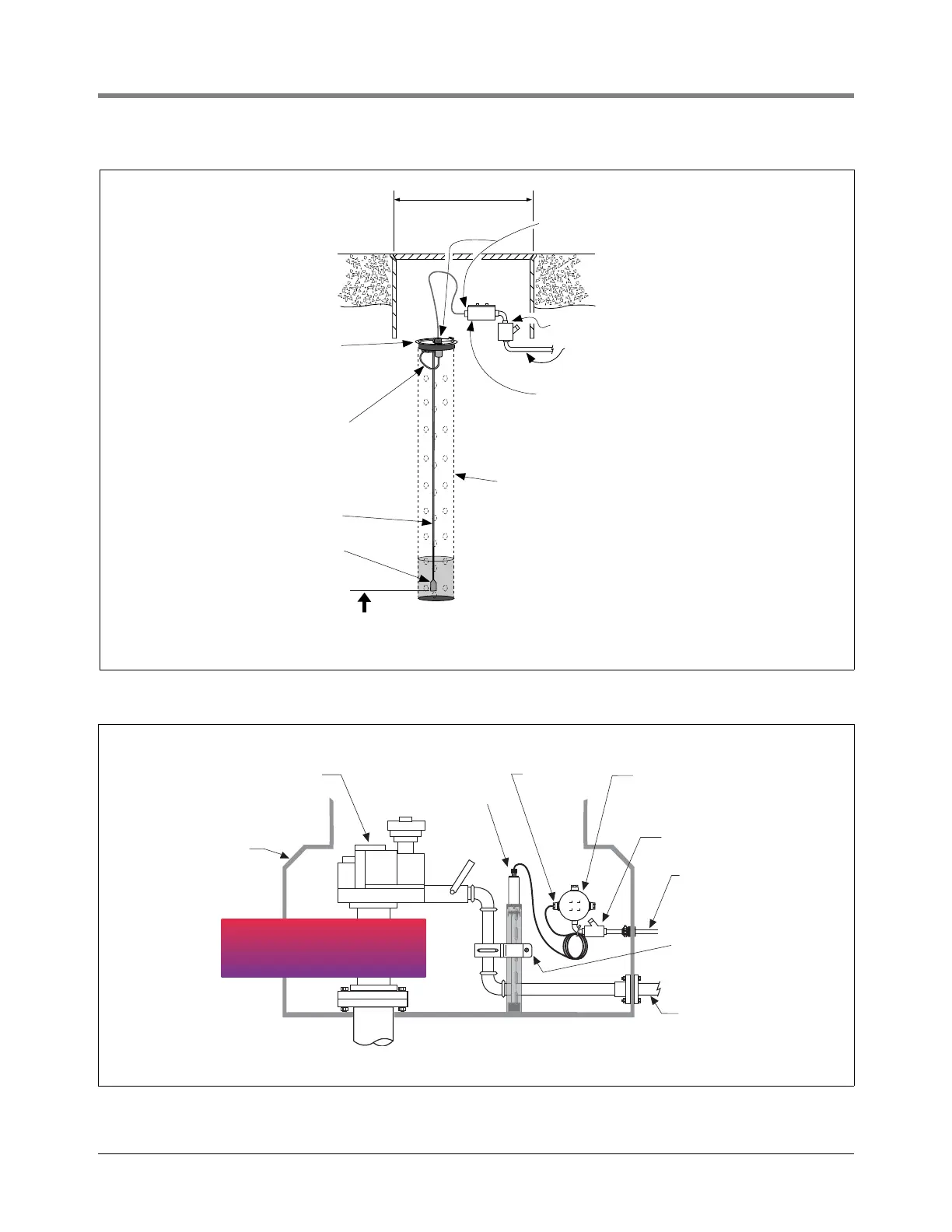
Figure 44. Example Groundwater Sensor Installation
Figure 45. Example Mag Sensor Installation
Cord grip
Weatherproof junction box with
1/2-inch N.P.T. threads (16 cubic
inch volume minimum)
14'' min. dia.
manhole
Seal-off
sensors\gwsinst.eps
1/2'' rigid conduit (to Console)
Extra sensor length
should not exceed
2-feet
Sensor well cap
w/ locking handle
Suspend water float 2''- 4'' above bottom of well.
NOTE: Water float must be submerged or console
will indicate WATER OUT alarm.
Sensor
Perforated PVC
monitoring well
housing
Water float
Submersible
pump
Containment
sump
Mag Sensor
Weatherproof
junction box
1/2'' Rigid
conduit
to console
Seal-off
sensors\magsensor.eps
Cord grip
Product line
Brackets, clamp, etc.
from optional Universal
sensor mounting kit
IMPORTANT!
DO NOT MOUNT SENSOR TO
FLEXIBLE PRODUCT LINE.
IMPORTANT!
DO NOT MOUNT SENSOR TO
FLEXIBLE PRODUCT LINE.

 Loading...


