Connecting Probe/Sensor Wiring to Consoles TLS-350/ProMax/EMC Consoles
69
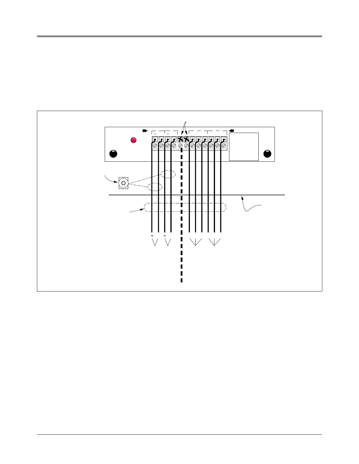
I/O COMBINATION MODULE - POWER BAY
The I/O Combination Module can accept two dry-contact switch closure inputs from an external device such as a
line leak detector or well monitoring system [Figure 67].]
For each external input, connect a shielded cable consisting of two #18 AWG conductors to the appropriate input
terminals on the module.
Figure 67. I/O Combination Module Wiring
INPUT
I/O COMBINATION MODULE
RELAY
consoles\iocmw.eps
Console
Attach Cable Shield to Ground
Lug Closest to Conduit Entry
+ +
InputInput
Shielded
Cables
External Input
Wiring
#18 AWG
NC NO C
External
Device
Relay Output
Wiring
#14 AWG
NC NO C
External
Device
Not Used
Rigid Conduit (enters
Console through a
Power Bay knockout)
+
+
1 2 3
NC NO C
3
NC NO C
44
RELAY RATINGS
FORM C CONTACTS
120 VAC 2A MAX
24 VDC 2A MAX
FUSE RATINGS
2A 250VAC TYPE T
(SLO-BLO)
 Loading...


