Connecting Probe/Sensor Wiring to Consoles TLS-350/ProMax/EMC Consoles
67
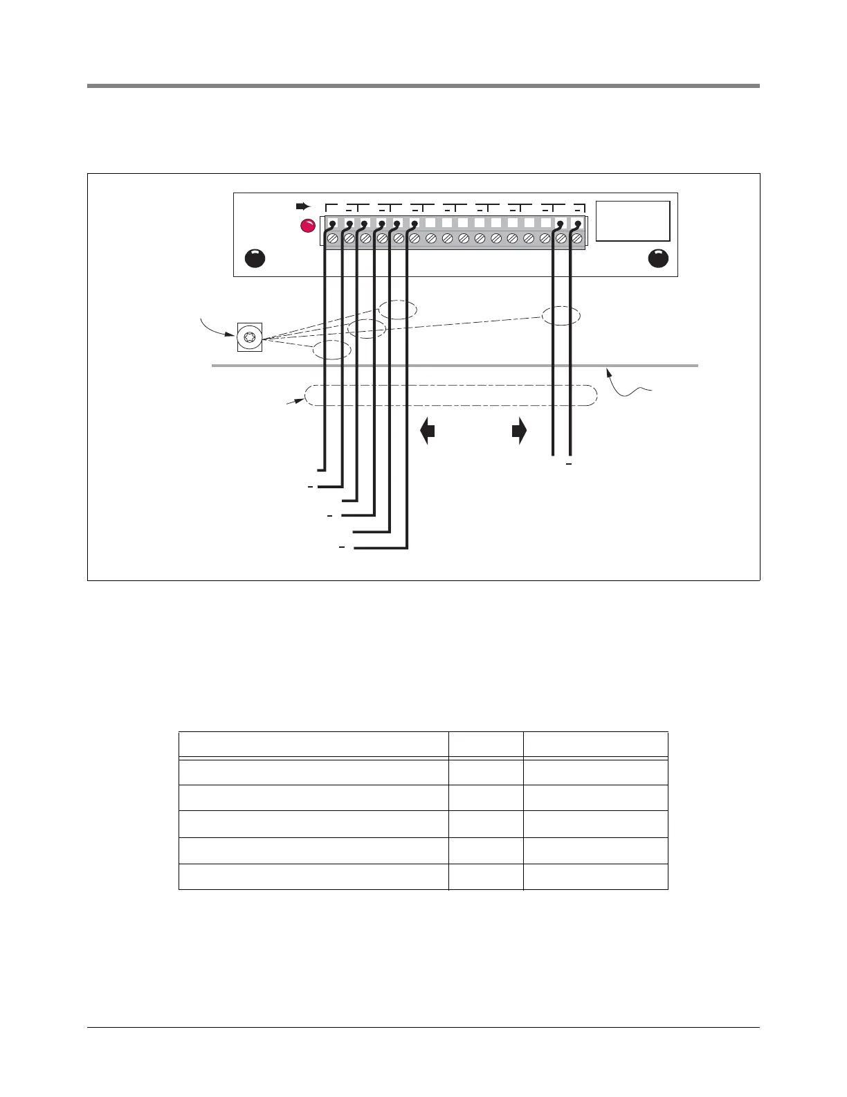
SMART SENSOR INTERFACE MODULE - I.S. BAY
Figure 65. Smart Sensor Interface Module
Connecting Devices
Connect sensors in the table below to the appropriate terminals on the Smart Sensor Interface module as shown in
Figure 65.
WIRING ADDITIONAL IS BAY MODULES
The connection diagram for Pressurized Line Leak Interface Modules (also an Intrinsically Safe bay module) is
covered in the PLLD Site Prep and Installation Manual which is shipped with that system.
Device Wires Observe Polarity
Mag Sensor 2 Yes
ISD Vapor Flow meter 2 Yes
ISD Vapor Pressure Sensor 2 Yes
Vacuum Sensor 2 Yes
Carbon Canister Vapor Polisher 2 Yes
Attach Cable Shields to Ground
Lug Closest to Conduit Entry
SMART
SENSOR
MAXIMUM
OUTPUT RATINGS
13 VDC
0.2 AMP
+ + + + + + + +
1 2 3 4 5 6 7 8
SMART SENSOR INTERFACE MODULE
consoles\smsnw.eps
Console
+
+
Mag Sensor
Vacuum
Sensor
ISD Flow Meter
+
ISD Pressure Sensor
+
Smart Sensor
(8 total)
Rigid Conduit
(enters Console
through an I.S. Bay
knockout)
 Loading...


