38
Sensor Installation
Sensor Installation Diagrams
General installation diagrams for various Veeder-Root sensors are shown in Figure 30 through Figure 47. When
installing sensors you must adhere to the procedures shown in these figures, unless a separate manual is shipped
with your sensor, in which case you should follow that manual’s installation guidelines. For those sensor
installations requiring the Universal Mounting Kit (P/N 331144-001), refer to Appendix B for suggested
attachment configurations.
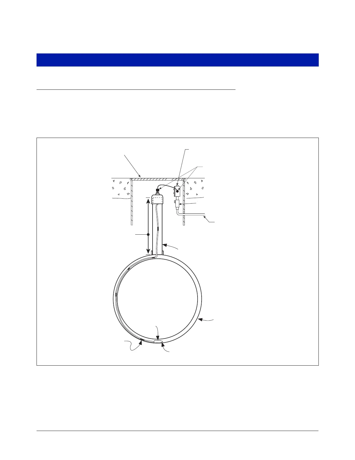
Figure 30. Example Interstitial Sensor Installation - Fiberglass UST
4'' dia. riser
Weatherproof junction box with
1/2-inch N.P.T. threads (16 Cubic
inch volume minimum)
14'' min. dia. manhole
Fiberglass tank
sensors\disfinst.eps
1/2'' rigid conduit (to Console)
Part number
Pull-cord eyelet
Sensor Switch must
reach bottom of tank
Riser length
.
.
.
.
.
..
.
.
.
.
.
.
.
.
.
.
.
.
..
.
.
.
.
.
.
.
Seal-off
Cord grips

 Loading...


