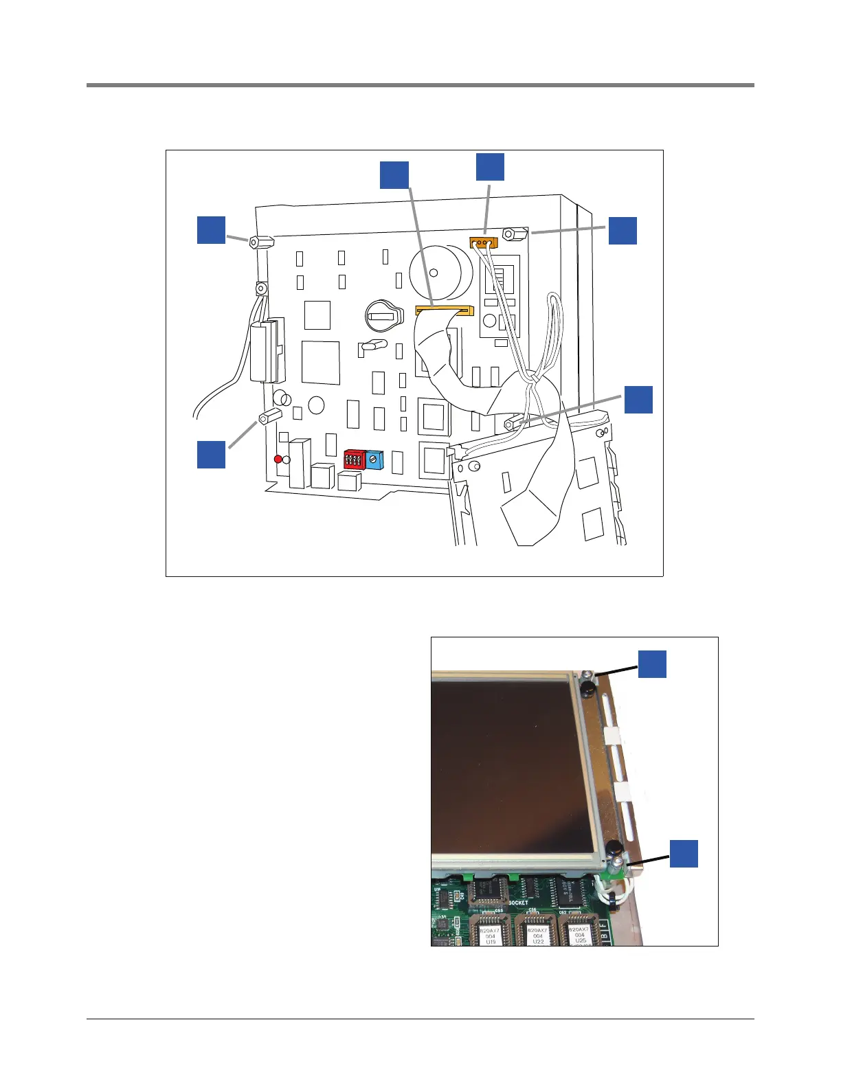
Figure 5. Attaching the display to the CPU board
1 Get the four T-10 screws, spacers and washers you
saved when removing the display from the old CPU
board (items 1 and 2 in Figure 2).
2 Get the display and attach its 2-wire cable plug to the
connector on the CPU board (item 1 in Figure 5).
3 Push the display’s ribbon cable into its connector on
the CPU board (item 2 in Figure 5).
4 Position the display over the standoffs (item 3 in
Figure 5) and replace the 4 screws and 2 spacers
(used under right side display attaching screws only -
see plastic spacers (item 4 in photo at right).