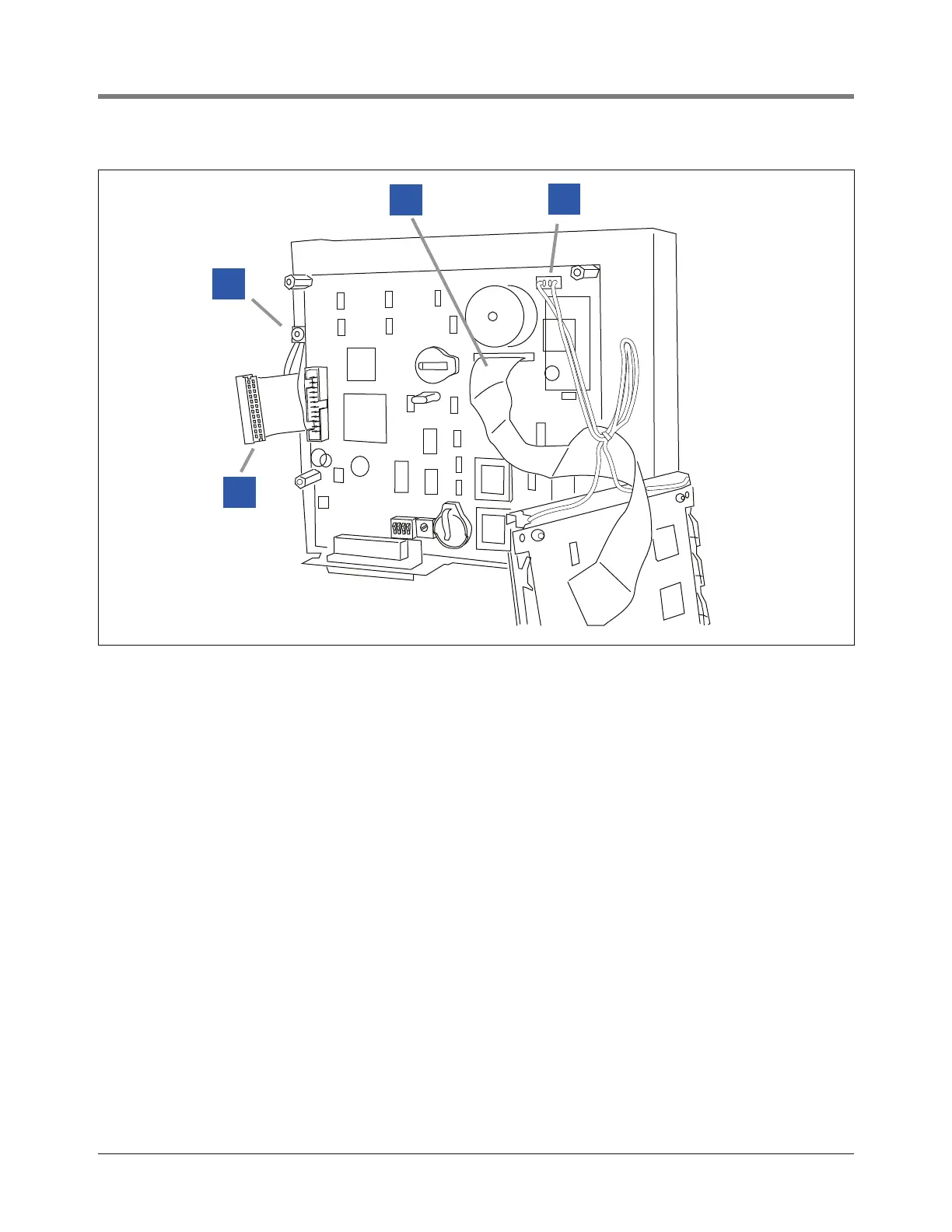
Figure 3. Removing the display
1 Hold the display and pull up the ribbon cable from its
connector on the CPU board (item 1 in Figure 3) and
remove the 2-wire plug (item 2 in Figure 3) at the top
of the CPU board. Carefully set the dis play aside.
2 Using the T-15 torx wrench, remove the ground wire
saddle clamp on the inner door (item 3 in Figure 3).
3 Remove the ribbon cable from its connector on the
edge of the CPU board (item 4 in Figure 3). Notice the
orientation of the ribbon cable in the connector as it will
connect to the new CPU board in the same way.
4 Remove and retain the top and bottom T-15 screws
and washers (item 1 in Figure 1) from the left side of
the console door. Remove and discard the door.
5 While pushing the ground wire and ribbon cable
through the slot in the inner door, remove the CPU
board/inner door assembly and discard.