1 Get the new TLS2P CPU board/inner door assembly
from the kit. Get the two T-15 torx shoulder screws
you removed from the right side of the door earlier.
2 Get the static protecting wrist strap from the kit and slip
the looped end around one wrist and connect the other
end to side of the console.
3 Remove the CPU board/inner door assembly from its
packing and push the ground cable and ribbon cable
through the right side opening in the inner door
assembly and place the inner door assembly on the
console and screw in the two right-side T-15 torx
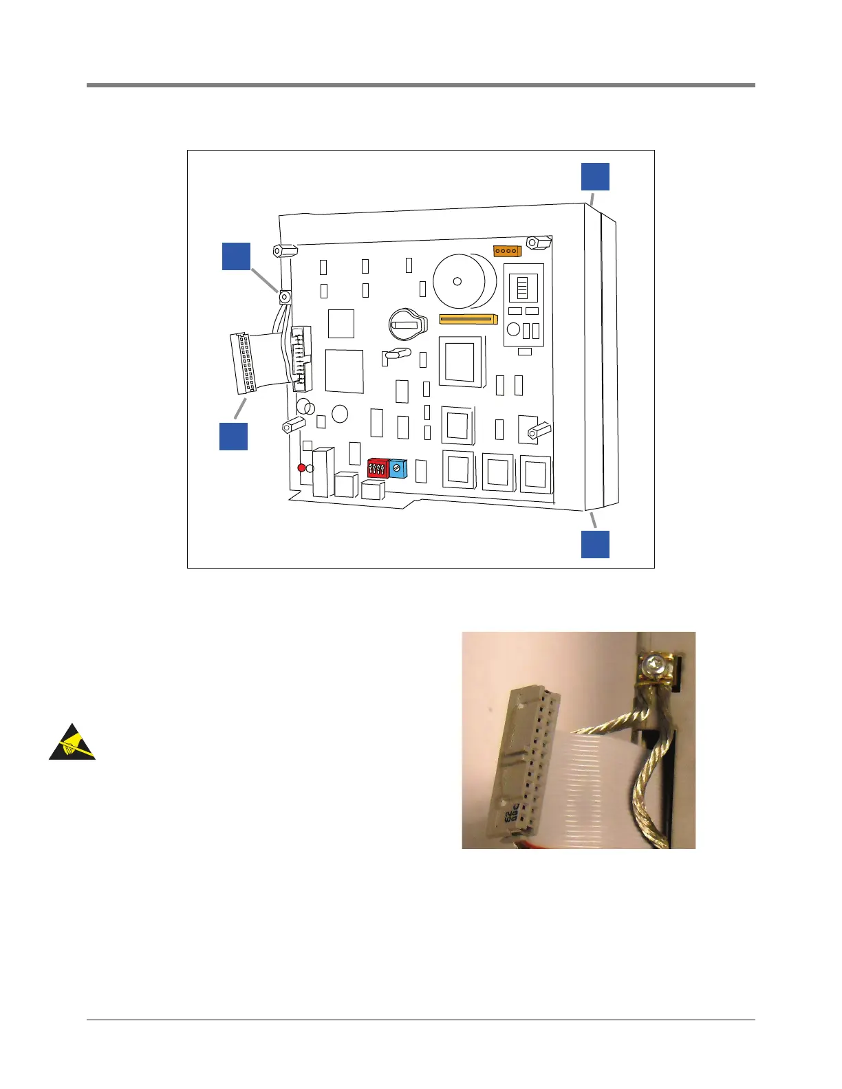
shoulder screws (item 1 in Figure 4), snug but not tight.
Reattach the grounding strap to the bare metal on the
top of the inner door.
4 Loosen the ground wire saddle clamp on the inner door
(item 2 in Figure 4) and loop the ground wire through it
and tighten securely (see photo at right). The other end
of the ground wire will attach to the new door’s
grounding saddle clamp.
5 Connect the ribbon cable (item 3 in Figure 4) to the
connector on the left side of the new CPU board.