EasyManua.ls Logo

Veeder-Root TLS2 - Control Drawing Overview; System Site Layout Diagram

Veeder-Root TLS2
13 pages
Print Icon
To Next Page IconTo Next Page
To Previous Page IconTo Previous Page
Loading...
Installation of Upgrade Kit Safety Precautions
4
Figure 2. Disconnecting the display assembly from the CPU board
983-2.eps
1
1
2
2
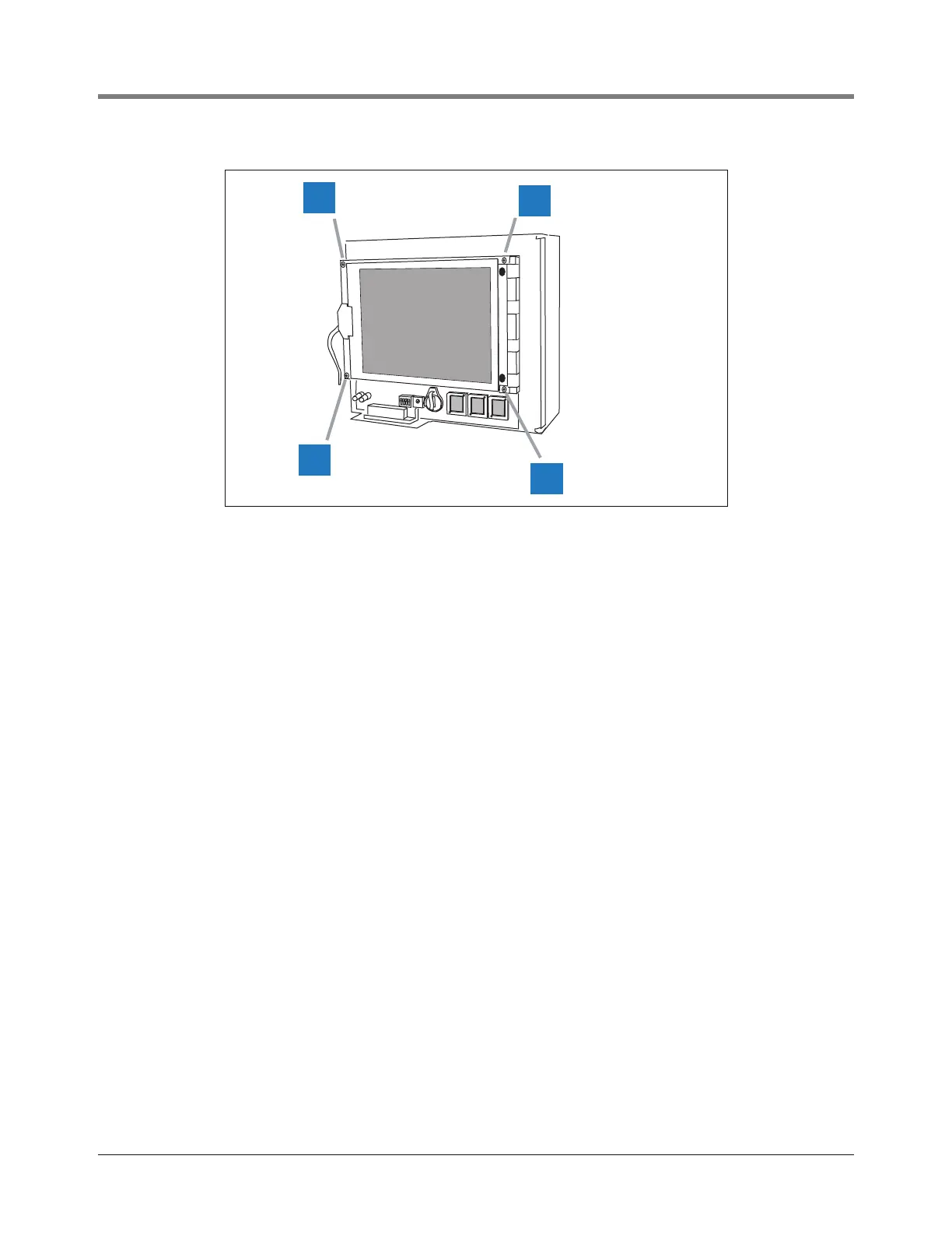
1 Remove and retain the four T-10 screws, spacers and
washers (items1 and 2 in Figure 2) attaching the
display to the CPU board. Retain the two shorter
screws (0.5” long - item 2 in Figure 2) and all of the
washers. Carefully remove the last screw while
holding the display assembly. Lower the display until
it is supported by its two cables.

Other manuals for Veeder-Root TLS2

Related product manuals