15
4 Mounting
VEGAPULS C 23 • Modbus and Levelmaster protocol
58349-EN-200806
For nozzle mounting, the nozzle should be as short as possible and
itsendrounded.Thisreducesfalsereectionsfromthenozzle.
The antenna edge should protrude at least 5 mm (0.2 in) out of the
nozzle.
≥ 5 mm
(
0.20")
Fig. 11: Recommended socket mounting of VEGAPULS C 23
Ifthereectivepropertiesofthemediumaregood,youcanmount
VEGAPULS C 23 on sockets longer than the antenna. The socket end
should be smooth and burr-free, if possible also rounded.
Note:
When mounting on longer nozzles, we recommend carrying out a
false signal suppression (see chapter " Parameter adjustment").
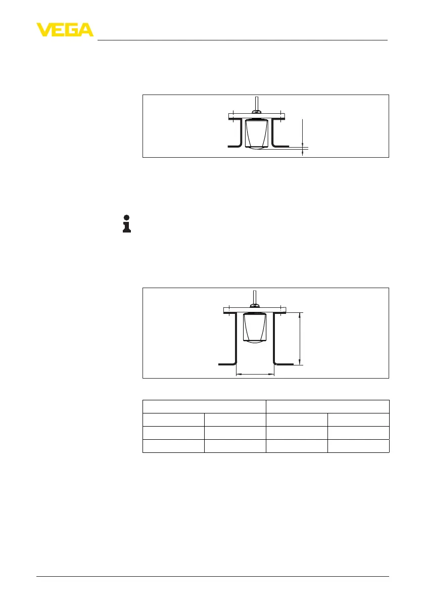
Youwillndrecommendedvaluesforsocketheightsinthefollowing
illustration or the table. The values come from typical applications.
Deviating from the proposed dimensions, also longer sockets are
possible, however the local conditions must be taken into account.
d
h
Fig. 12: Socket mounting with deviating socket dimensions
Socket diameter d Socket length h
80 mm 3" ≤300mm ≤11.8in
100 mm 4" ≤400mm ≤15.8in
150 mm 6" ≤600mm ≤23.6in
The mounting location of the radar sensor should be a place where no
otherequipmentorxturescrossthepathoftheradarsignals.
Vessel installations, such as e.g. ladders, limit switches, heating spi-
rals, struts, etc., can cause false echoes and impair the useful echo.
Make sure when planning your measuring point that the radar sensor
has a " clear view" to the measured product.
In case of existing vessel installations, a false signal suppression
should be carried out during setup.
Nozzle
Vessel installations

 Loading...


