20
PHTM II
Installation, Operating & Service Instructions
110331-01 - 5/20
Boiler
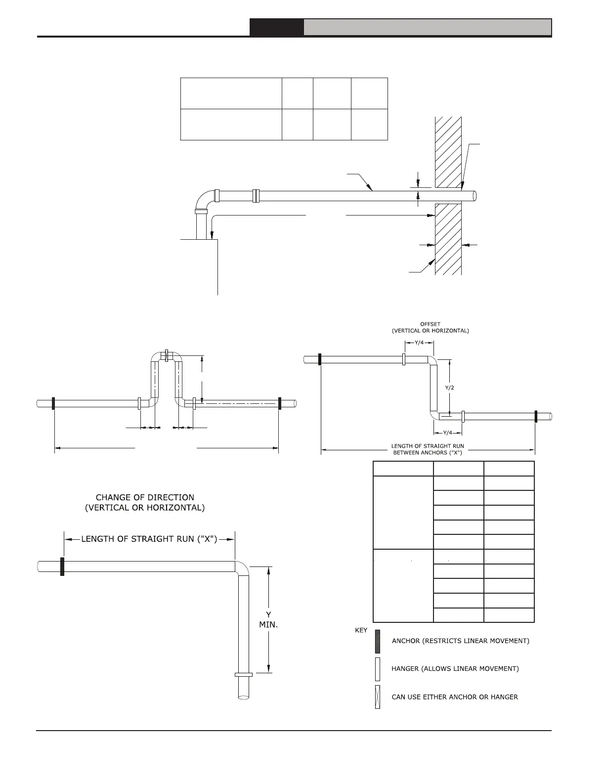
66" Min
(168cm)
One end of
opening may
be closed
PVC Vent Pipe
Wall
*Wall must be of non-combustible construction
Maximum Wall
Thickness ("T")
Minimum air space
around pipe ("C")
2"*
(50mm)
6"
(150mm)
12"
(305mm)
0"*
(0mm)
1"
(25mm)
1-3/4"
(45mm)
"C"
"T"
Length of straight run
between anchors ("X")
Loop
(horizontal only)
(top view)
Y/5
6" (150mm)
Min
6" (150mm)
Min
2Y/5
7 General Venting (continued)
Figure 7-15: CPVC/PVC Venting Expansion Loops
Figure 7-14: PVC Venting Wall Penetration Clearance
Pipe Dia, in. X, ft. (m) Y, in. (cm)
2
20 (6.1) 41 (104)
30 (9.1) 50 (127)
40 (12.2) 58 (147)
50 (15.2) 65 (165)
60 (18.3) 71 (180)
3
20 (6.1) 50 (127)
30 (9.1) 61 (155)
40 (12.2) 70 (178)
50 (15.2) 79 (201)
60 (18.3) 86 (218)