42
PHTM II
Installation, Operating & Service Instructions
110331-01 - 5/20
13 Field Wiring
DANGER
Electrical Shock Hazard.
• Disconnect electrical supply before
installing or performing maintenance.
• Electrical power may be supplied
from more than one circuit.
•Lock out all electrical boxes with padlock once
power in turned off.
!
WARNING
Electrical Shock Hazard.
All wiring and grounding must conform to
requirements of authority having jurisdiction or,
in absence of such requirements, to National
Electrical Code/NFPA 70 or Canadian Electrical
Code, Part 1 (CSA C22.1 - latest edition).
• Make electrical connections according
to boiler's wiring diagram and instructions.
Failure to properly wire electrical connections
to the boiler may result in severe personal
injury, death or substantial property damage.
• Protect each boiler circuit with a
properly sized over-current device.
• Never jump out or bypass any safety or
operating control or component of this boiler.
!
NOTICE: Internal wiring diagrams contained in
this manual are for reference only. Each boiler is
shipped with a wiring diagram sheet within boiler
literature packet. Read, understand and follow this
wiring diagram and wiring diagrams of any field
supplied controls.
NOTICE: Boiler is equipped with a UL 353
listed high water temperature limit function. This
limit provides boiler shutdown in event boiler
water temperature exceeds set point of control.
Certain local codes require an additional water
temperature limit. If necessary, install an additional
water temperature (Honeywell L4006 Aquastat).
Wire as indicated in Figure 13-3.
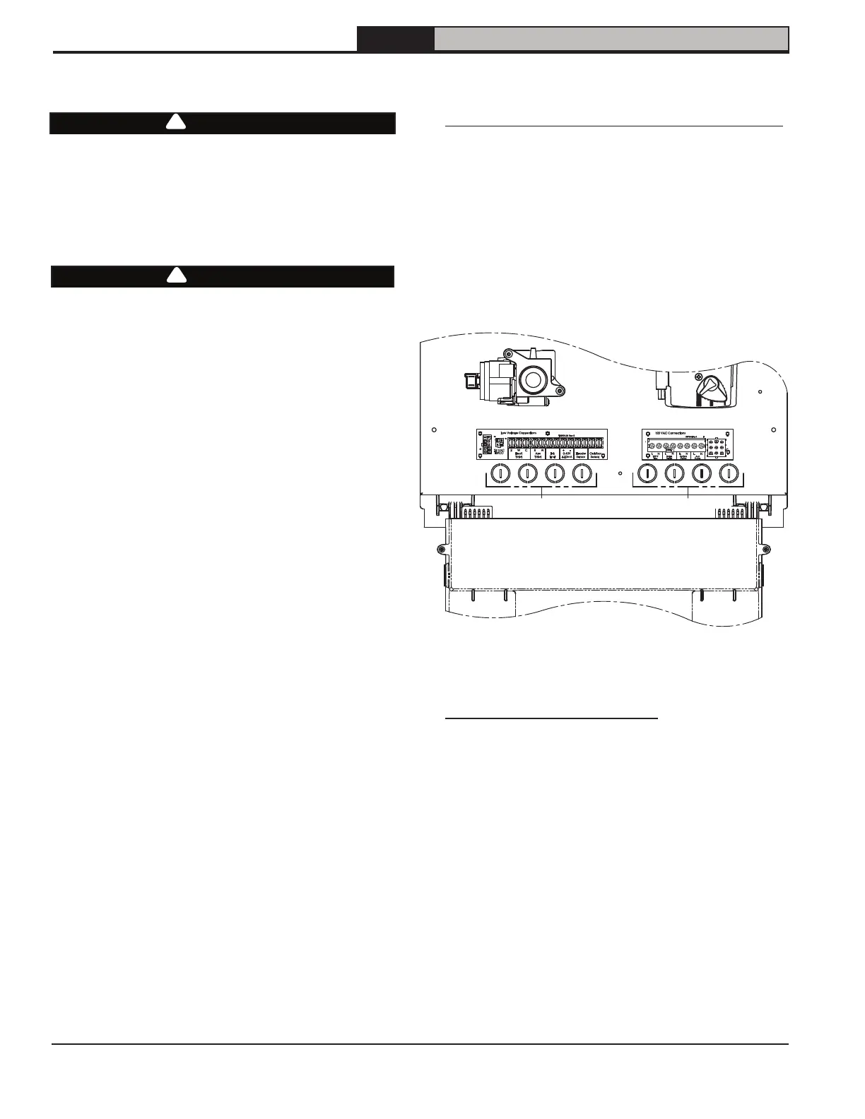
Locating Field Connection Terminal Strips
Field connection terminal strip locations are shown in
Figure 13-1. To access terminal strips:
1. Remove front door. Front door is removed by
first loosening two thumb screws located
under front of door.
2. Disconnect igniter wire at burner door.
3. Pull control enclosure forward. (This requires
undoing tether on right hand side.)
Figure 13-1: Location 120VAC and low voltage
connection boards
Low Voltage Connection Board
120 VAC Connection Board
Gas
Valve
Combi
Pump
Opened Control
Enclosure
Jacket Knockouts Jacket Knockouts
Field 120VAC Connections
A. Provide a dedicated circuit for boiler of 15A
or greater. A service switch is recommended
and is required by many local codes.
Locate this switch in accordance with
local codes or, in absence of such
requirements in a location where it
can be safely accessed in an emergency.
B. All 120VAC connections to boiler are made
on 120VAC Connections terminal strip (see
Figure 13-2) located on right side of bottom
panel. Route all 120 VAC wiring through
conduit knock out holes located on right
side in front of terminal strip.