46
PHTM II
Installation, Operating & Service Instructions
110331-01 - 5/20
WARNING
Burn Hazard.
Never exceed maximum allowable working
pressure on heat exchanger ASME plate. (50
psig (210 kPa) A 30 psig safety relief valve is
included with this boiler.
15 Start-Up and Checkout
Heating System Cleaning and Treatment
1. Prior to fill, flush entire heating system to remove
sediment, flux, and traces of boiler additives.
2. Clean with approved cleaners such as the
following or its equivalent:
• Fernox Cleaner F3 (for new heating systems)
• Sentinel x300 System cleaner (for new heating
systems)
• Sentinel X400 System Restorer (for old closed
loop hydronic systems)
Refer to instructions supplied with cleaner for
proper dosage and use.
CAUTION
Component Damage.
Avoid use of petroleum based boiler additives
and ester-based oils/lubricants. These could
attack seals in both boiler and system which
could result in property damage.
Fill Water Quality
NOTICE: Make sure system is filled with water
meeting the following criteria:
• Hardness less than 7 grains/gallon.
• pH between 6.5 and 9.5 (for systems containing
aluminum components, between 6.5 and 8.5)
• Chlorides less than 200 PPM. If fill water is
drawn from a system containing a water softener,
test a sample of the water to confirm that this
criteria is met.
Following appropriate water chemistry guidelines will
help extend the life of appliance by reducing effects
of lime scale buildup and corrosion. which could void
warranty.
NOTICE: Minimize introduction of make-up water,
dissolved oxygen, and contaminants into boiler by
following installation guidelines outlined in Appendix
B: Water Quality and Boiler Additives.
Freeze Protection
If freeze protection is required see Appendix B for
additional information.
Fill Water System
1. Fill system ensuring water quality meets
requirements of this manual.
2. Fill to correct system pressure. Pressure will vary
with each application.
3. Pressurize system to at least 12 psi at boiler.
!
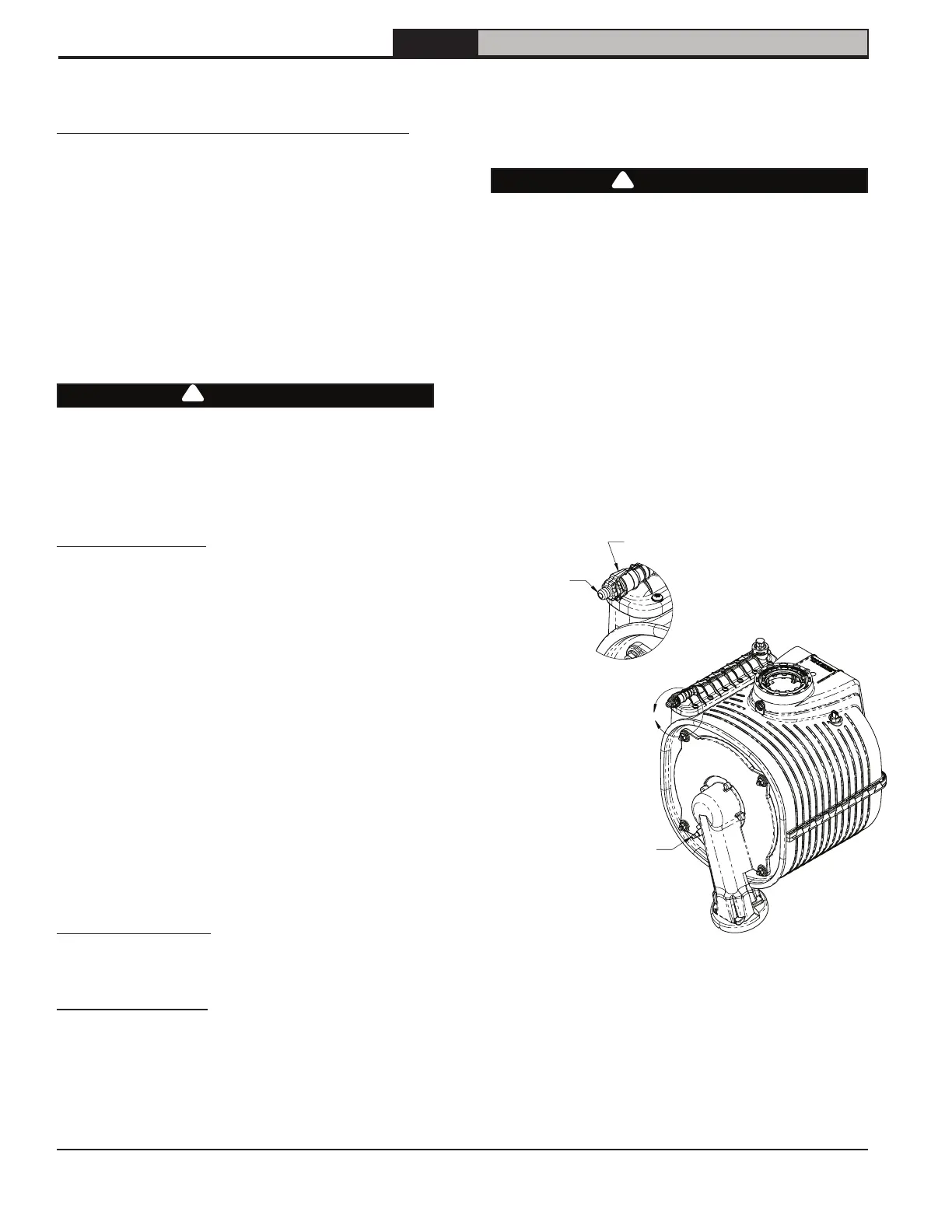
5. Eliminate air in boiler by bleeding from heat
exchanger manual air vent on top left side of heat
exchanger (Figure 15-1).
A. Use 1/4 in. (6 mm) ID tubing connected to
hose barb and route tubing to a safe draining
location.
B. Turn vent counter clockwise and allow heat
exchanger to vent until a steady stream of
water is observed.
C. Close vent and remove hose.
Figure 15-1: Manual Air Vent Location
6. Isolate each zone to purge air confirming that
heating system and boiler are completely filled.
7. Verify automatic air vent located on internal piping
is open and remains open to atmosphere. See
Figure 4-1 for location.
!
A
Flame Rod
Detail A
(Scale 2:1)
Manual Air Vent
Confirm 1/4" ID
tubing is connected
to hose barb. Route
tubing to a safe place
away from controls
before opening vent.
4. Verify air pressure in expansion tank is equal to
system pressure.